Wire testing machine with wire processing function

A testing machine and testing mechanism technology, applied in the direction of applying stable tension/pressure to test material strength, measuring devices, analyzing materials, etc., can solve problems such as the inability to realize wire processing and the inability to guarantee the accuracy of wire test results, etc., to increase Processing function, the effect of increasing practicability

Pending Publication Date: 2021-10-08
合肥吉顺新能源科技有限公司
View PDF8 Cites 1 Cited by
  • Summary
  • Abstract
  • Description
  • Claims
  • Application Information

AI Technical Summary

Problems solved by technology

[0007] The present invention proposes a wire testing machine with the function of processing wire, which solves the problem that the wire detection device in the prior art can only test the single performance of the wire, cannot guarantee the accuracy of the wire test results, and cannot realize the processing of the wire

Method used


Image

  • Wire testing machine with wire processing function
  • Wire testing machine with wire processing function
  • Wire testing machine with wire processing function

Examples


Embodiment 1

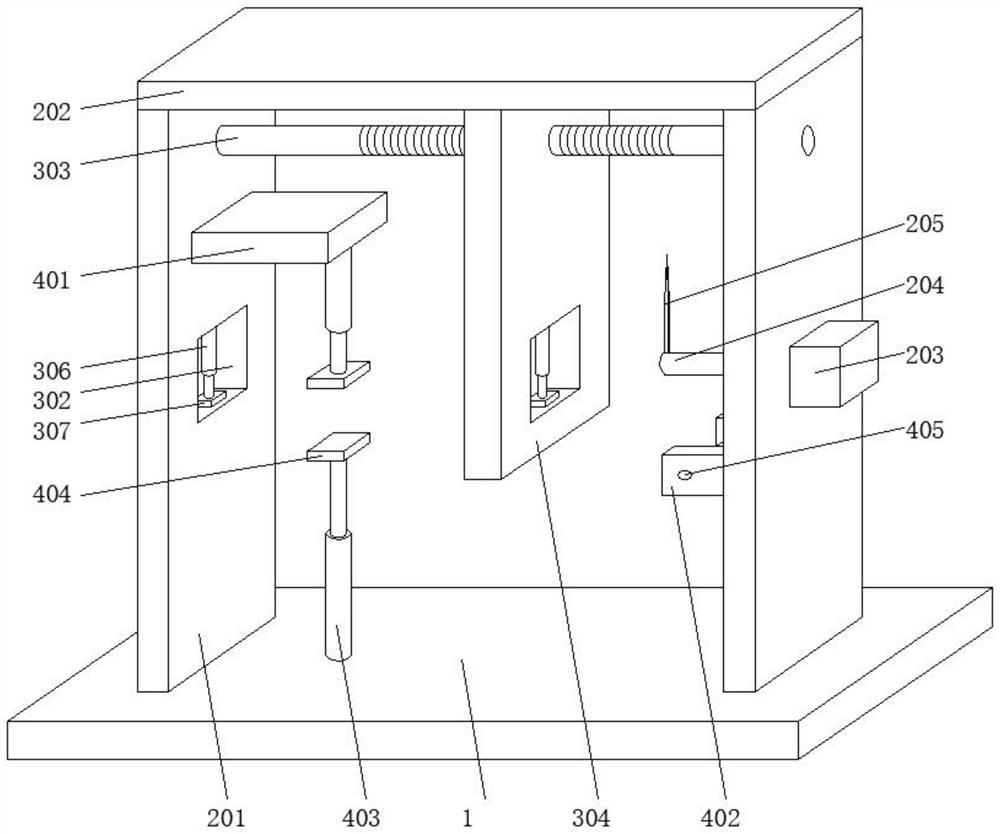
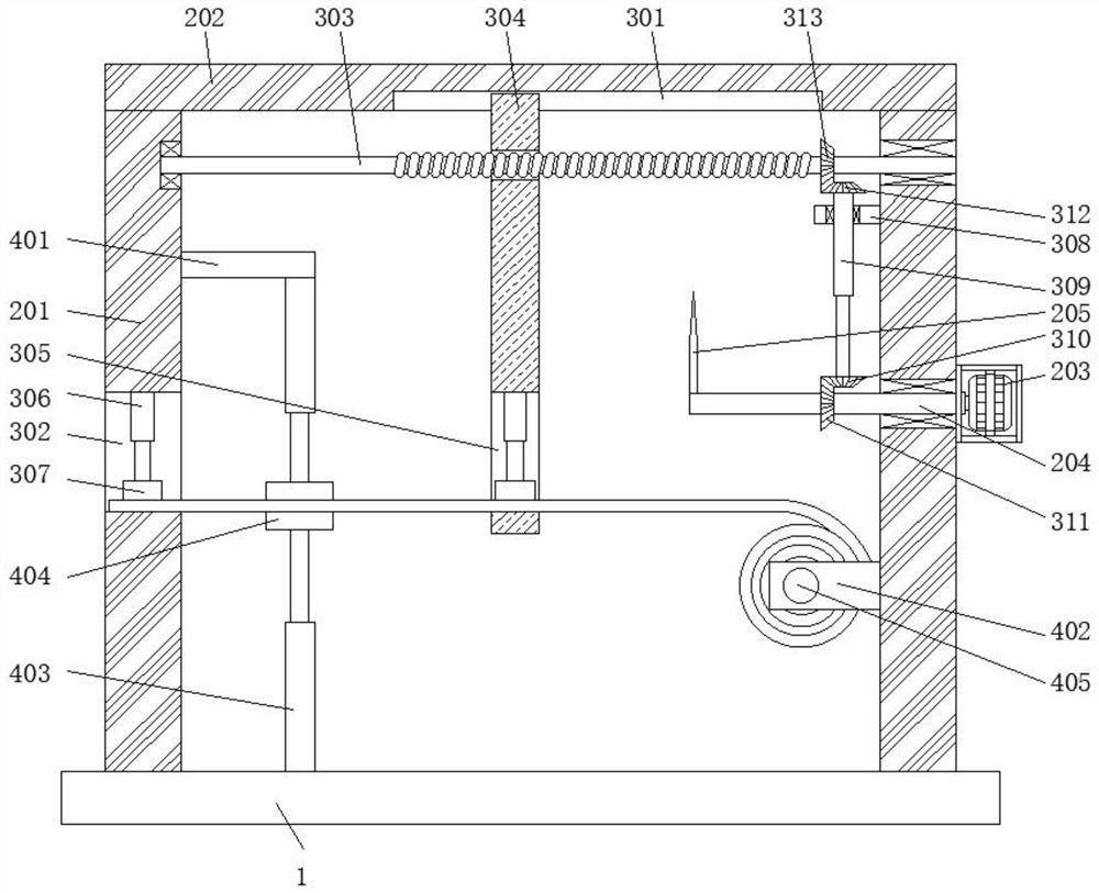
[0032] A wire testing machine with the function of processing wire, including a base 1, and also includes a wire cutting mechanism, a tensile testing mechanism, and a compressive testing mechanism; the wire cutting mechanism is set on the top of the base 1, and the wire cutting mechanism is used for wire processing , the wire cutting mechanism includes a support frame 201 and a top plate 202, the support frame 201 is symmetrically fixed on the top of the base 1, and the top plate 202 is fixed on the top of the two support frames 201; the tensile testing mechanism is located between the support frame 201 and the top plate 202 Between them, the tensile testing mechanism is used for tensile testing of the wire; the compressive testing mechanism is provided on the base 1 and the supporting frame 201, and the compressive testing mechanism is used for testing the compressive and bending resistance of the wire.

[0033] Preferably, a motor 203 is affixed to the right side of the right...

Embodiment 2

[0036] The difference from Example 1 is that it also includes the following:

[0037] The tensile testing mechanism comprises a limit groove 301, a vertical groove 302 and a long rod 303, the limit groove 301 is arranged at the bottom of the top plate 202, the vertical groove 302 is arranged on the left support frame 201, and the long rod 303 is rotatably connected to two supports. Between racks 201.

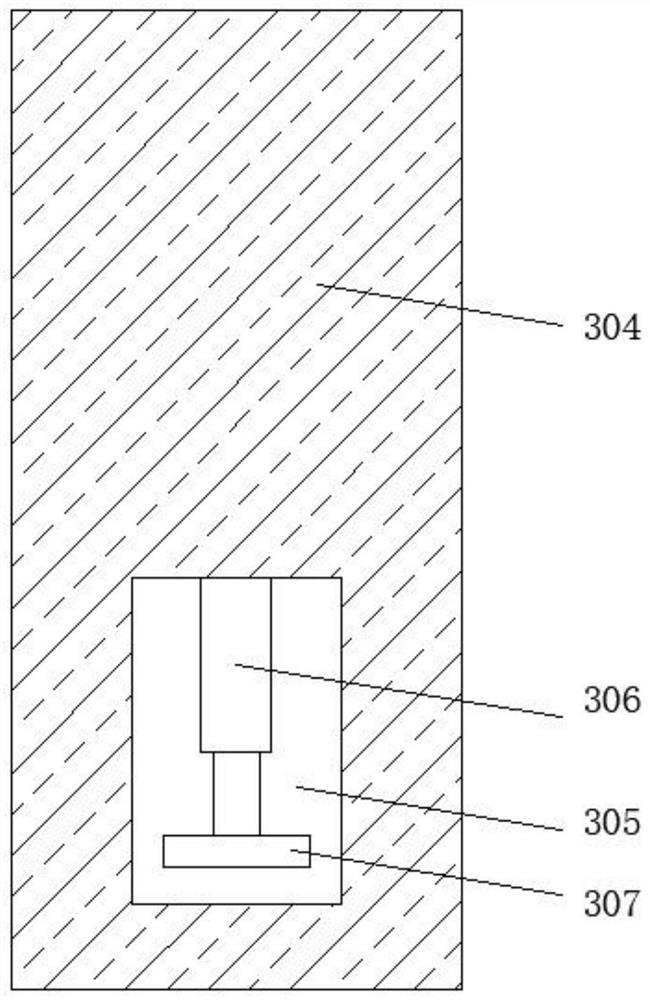
[0038] Preferably, the long rod 303 is provided with a threaded groove, the long rod 303 is threadedly connected with a moving plate 304, the moving plate 304 is provided with a hollow groove 305, and the inside of the vertical groove 302 and the hollow groove 305 are fixedly connected with a first hydraulic telescopic Rod 306, the bottom of the first hydraulic expansion rod 306 is fixedly connected with a fixed plate 307, the bottom of the fixed plate 307 is provided with a protrusion, and the right fixed plate 307 is provided with a tension tester.

[0039] The first hydrauli...


PUM


Abstract

The invention relates to the technical field of wire rod testing machines, and particularly discloses a wire rod testing machine with a wire rod processing function, which comprises a base, a wire rod cutting mechanism, a tensile testing mechanism and a compression testing mechanism. The wire rod cutting mechanism is arranged at the top of the base, the wire rod cutting mechanism is used for processing wire rods, the wire rod cutting mechanism comprises supporting frames and a top plate, the supporting frames are symmetrically and fixedly connected to the top of the base, and the top plate is fixedly connected to the tops of the two supporting frames; and the tensile testing mechanism is arranged between the supporting frames and the top plate. According to the invention, the wire rod is wound on the winding roller, the two first hydraulic telescopic rods are used for driving the fixing plate to move downwards to fix and clamp the two ends of the wire rod, the motor is used for driving the cutting knife to rotate, cutting of the wire rod is achieved, later function detection of the wire rod is facilitated, the moving plate moves rightwards to drive the wire rod to stretch, and the tensile function test of the wire rod is achieved. And meanwhile, the wire processing function is added, and the practicability of the device is improved.

Description

technical field [0001] The invention relates to the technical field of wire testing machines, in particular to a wire testing machine with the function of processing wires. Background technique [0002] Wire rod is the smallest section size of hot-rolled section steel. In my country, the hot-rolled round steel supplied in coils with a diameter of 5-9 mm and a total of eight specifications is called wire rod. Wire rod is also called wire rod because it is delivered in coils. The concept of wire rod in foreign countries is slightly different from that in my country. There are other shapes besides circular cross-section, and its diameter is inconsistent due to different demand conditions and production technology levels. According to the different rolling mills, it can be divided into two types: high-speed wire rod (high wire) and ordinary wire rod (common wire). [0003] Wire rods are generally made of ordinary carbon steel and high-quality carbon steel. According to the s...

Claims


Application Information

Patent Timeline
Patent Type & Authority Applications(China)
IPC IPC(8): G01N3/12G01N3/04
CPCG01N3/12G01N3/04
Inventor 王让祥
Owner 合肥吉顺新能源科技有限公司
Why Eureka
Try Eureka