Two-dimensional super-resolution radar imaging method based on fusion technology

A radar imaging and super-resolution technology, which is used in the reflection/re-radiation of radio waves, the use of re-radiation, measurement devices, etc. Radar azimuth resolution is low and other problems, to save manpower, material and financial resources, improve radar resolution, and easy methods

Active Publication Date: 2021-10-08
AEROSPACE INFORMATION RES INST CAS
View PDF3 Cites 3 Cited by
  • Summary
  • Abstract
  • Description
  • Claims
  • Application Information

AI Technical Summary

Problems solved by technology

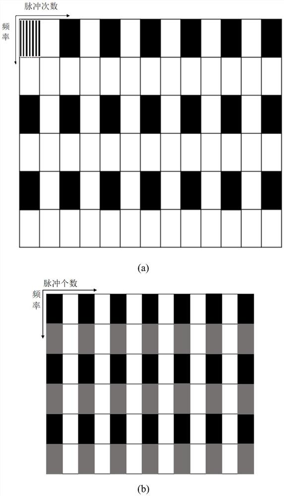
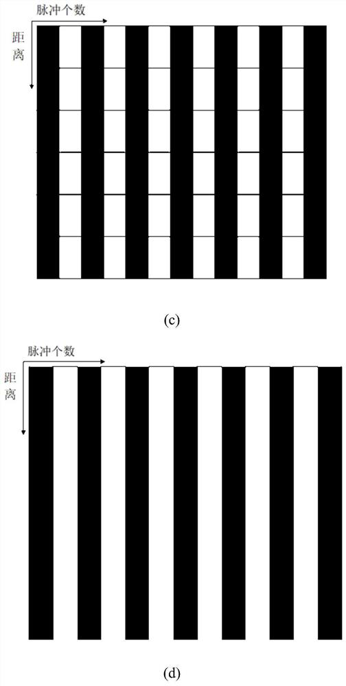
[0005] In order to solve the problems of low azimuth resolution of existing radars and limited two-dimensional super-resolution capability of radar systems, as well as the difficulty of directly realizing large-bandwidth signals and the incomplete acquisition of multi-functional radar pulse echoes, the present invention proposes a method based on The two-dimensional super-resolution radar imaging method of fusion technology regards multiple sub-pulse segment echoes as multi-subband radar echoes, and then uses fusion technology to estimate the pulse echo with long-term accumulation angle from multiple pulse echo signals Signal, image the fused large-bandwidth long-coherent accumulation time signal, and obtain high-resolution and clear radar images
For the inaccurate estimation of the number of scattering centers on the target by existing methods, the present invention adopts a method for estimating the number of scattering centers based on the difference of echo singular values, and introduces the geometrical theory of diffraction (GTD) model into into the multi-subband fusion algorithm

Method used


Image

  • Two-dimensional super-resolution radar imaging method based on fusion technology
  • Two-dimensional super-resolution radar imaging method based on fusion technology
  • Two-dimensional super-resolution radar imaging method based on fusion technology

Examples


Embodiment Construction

[0044] The technical solutions in the embodiments of the present invention will be clearly and completely described below in conjunction with the accompanying drawings in the embodiments of the present invention. Obviously, the described embodiments are only part of the embodiments of the present invention, not all of them. Based on the embodiments of the present invention, all other embodiments obtained by persons of ordinary skill in the art without making creative efforts belong to the protection scope of the present invention.

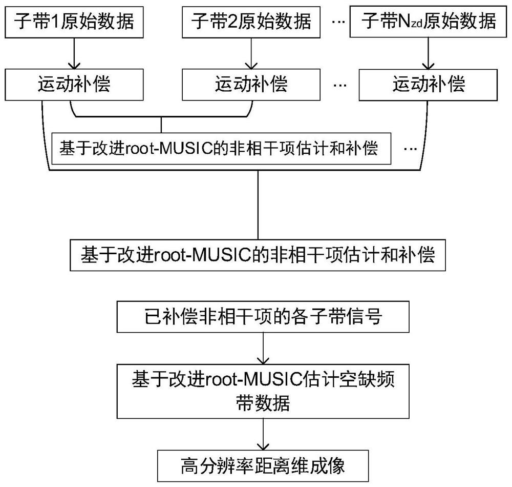
[0045] In order to make the purpose of the present invention, technical solutions and advantages clearer, the following combination figure 1 , figure 2The present invention is further described in detail with specific examples.

[0046] According to one embodiment of the present invention, a kind of two-dimensional super-resolution radar imaging method based on fusion technology is proposed, comprising the following steps:

[0047] Step 1: Obtai...


PUM


Abstract

The invention relates to a two-dimensional super-resolution radar imaging method based on a fusion technology. The two-dimensional super-resolution radar imaging method comprises the following steps of 1, receiving each sub-band radar signal in each sub-pulse time period; 2, carrying out motion compensation on the signal in each pulse time period; 3, representing the sub-band signals in the pulse time period by using a geometric diffraction model; 4, selecting the sub-band signal distributed in the lowest frequency band as a reference signal, and calculating and compensating the incoherent terms between other sub-band signals and the sub-band signal based on the improved root-MUSIC; 5, based on the improved root-MUSIC, estimating the geometric diffraction model parameters of the large-bandwidth signals from all the sub-band signals subjected to incoherent item compensation; 6, substituting the estimated large-bandwidth signal parameters into the geometric diffraction model to reconstruct a large-bandwidth signal; 7, carrying out distance dimension compression imaging on the estimated large-bandwidth signal; and 8, for a plurality of sub-pulse echo bands corresponding to each distance unit, obtaining a pulse echo signal of long pulse accumulation time, and performing azimuth compression to realize the azimuth super-resolution.

Description

technical field [0001] The invention relates to the technical field of radar imaging, in particular to a two-dimensional super-resolution radar imaging method based on fusion technology. Background technique [0002] Microwave radar observes the target by emitting electromagnetic waves on the target and then processing the reflected electromagnetic waves of the target, so it has the ability to work all day and all day. Compared with optical detectors, microwave radar can detect, track and identify targets in harsh environments. effect. [0003] In order to obtain finer structure information of the target, it is necessary to improve the range and azimuth resolution of the microwave radar. The range resolution can be improved by transmitting a large bandwidth chirp signal, and the azimuth resolution can be improved by increasing the imaging accumulation angle. In order to improve the range resolution of the existing radar system under the condition of minimum hardware consu...

Claims


Application Information

Patent Timeline
Patent Type & Authority Applications(China)
IPC IPC(8): G01S13/89G01S7/41
CPCG01S13/89G01S7/41Y02A90/10
Inventor 李王哲蒋文
Owner AEROSPACE INFORMATION RES INST CAS
Why Eureka
Try Eureka