Method for producing yarn using a ring spinning frame, and ring spinning frame

A spinning frame and yarn technology, which is applied to spinning machines, continuous winding spinning machines, textiles and papermaking, etc. It can solve the problem of changing the number and size of balloons

Pending Publication Date: 2021-10-08
MASCHINENFABRIK RIETER AG
View PDF16 Cites 0 Cited by
  • Summary
  • Abstract
  • Description
  • Claims
  • Application Information

AI Technical Summary

Problems solved by technology

As the ring bar moves over the entire length of the spindle

Method used


Image

  • Method for producing yarn using a ring spinning frame, and ring spinning frame
  • Method for producing yarn using a ring spinning frame, and ring spinning frame
  • Method for producing yarn using a ring spinning frame, and ring spinning frame

Examples


Embodiment Construction

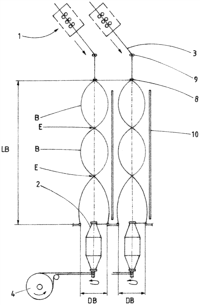
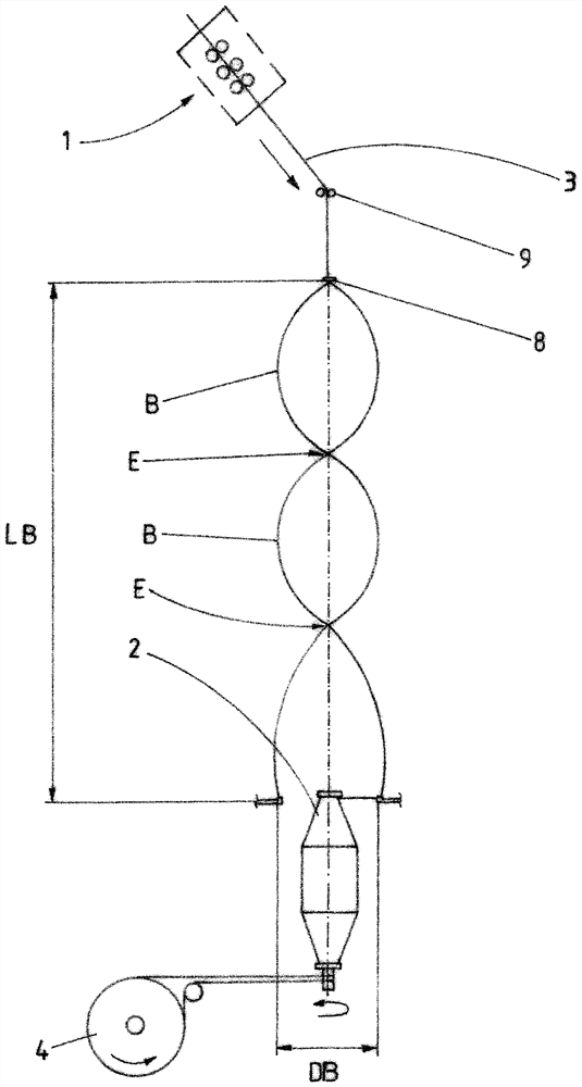
[0029] exist figure 1 , figure 2 A spinning station of a ring spinning frame (not shown) is schematically shown in . In the present method for producing yarn at a spinning station, the fiber composite material 3 is fed to the drafting system 1 and drawn as it passes through the drafting system 1 . The fiber composite material 3 is guided over the thread guide 8 and through the rotating traveler 5 , wherein the traveler 5 rests on the ring 6 , wherein the fiber composite material 8 is twisted and a yarn 12 is produced, and the yarn 12 is wound onto a sleeve 2 which is placed on a rotating spindle. The spindle 2 is driven by a spindle drive 4, which can be a single-spindle drive. In the specified method, the ring 6 is on a fixed ring plate and the spindle 2 is on a moving spindle rail.

[0030] as from figure 1 , figure 2It can be seen that in this case a helical path E of the fiber composite material 8 with two complete balloons B is produced between the thread guide ...


PUM


Abstract

The invention relates to a method for producing yarn at a spinning station of a ring spinning frame, in which a roving (3) is fed to a drawing frame (1) and, on passing through, is drawn and guided via a thread guide (8), the roving (3) is guided through a circulating traveller (5), the traveller (5) being situated on a ring (6), and the roving (3) undergoes rotation to produce a yarn (12), and the yarn (12) is wound onto a sleeve (2) which is placed on a rotating spindle. The ring (6) is situated on a stationary ring rail, and the spindle is situated on a moving spindle rail. A spiral path of the roving (3) with at least two balloons (B) is produced between the thread guide (8) and the traveller (5). The thread guide (8) is moved such that the same number of balloons (B) is always produced over the distance (LB) between the thread guide (8) and the traveller (5) during the spinning process.

Description

technical field [0001] The invention relates to a method of using a ring spinning frame for the production of yarn and a ring spinning frame according to the preambles of the corresponding independent claims. Background technique [0002] WO2018122625 discloses a spinning and / or twisting process in which the yarn forms a helical path with at least two balloons between the thread guide and the traveler. This method has no elements that define the balloon. [0003] GB1239477 shows a method for producing yarn by means of a ring spinning frame, in which a helical path of fiber composite material with at least two balloons is produced between the engagement point of the outlet roll (nip roll) and the traveler. The method has fixed and movable elements for delimiting the balloon, whereby, according to the figures, these elements do not have to be in permanent contact with the wire. As the ring bar moves over the entire length of the spindle, the number and size of the balloons d...

Claims


Application Information

Patent Timeline
IPC IPC(8): D01H1/02D01H1/42
CPCD01H1/02D01H1/422
Inventor H-J·屈斯特M·法尔纳
Owner MASCHINENFABRIK RIETER AG
Why Eureka
Try Eureka