
Oil well sand washing pump and using method thereof

A technology for sand washing and oil wells, applied in the direction of pumps, jet pumps, earthwork drilling and production, etc., can solve problems such as no jet formation, no filter structure, and pump inoperability, so as to avoid parts falling off, smooth liquid flow, and reduce edge The effect of stroke resistance loss

Pending Publication Date: 2021-10-12
SINOPEC SSC +2
View PDF4 Cites 0 Cited by
  • Summary
  • Abstract
  • Description
  • Claims
  • Application Information

AI Technical Summary

Problems solved by technology

Because the liquid used in the jet is difficult to ensure that there are no particles and other impurities in it, and these impurities can easily block the nozzle with a small aperture. wear or damage to components
[0004] Example 2: The patent titled "High Efficiency Jet Pump" (Application No. 201610121948.1) has an overly complex structure, and its liquid flow channels are too complicated, many (at least 3 flow channels), slender and curved, and there is no filter structure design. Because the liquid used by the jet is difficult to ensure that there are no impurities such as particles, and these impurities can easily block the nozzle with a small aperture, which is likely to block the flow channel and eventually interrupt the jet and make the pump unable to work; its structure lacks filter components , is the main reason that the liquid inlet is easy to block
[0005] Example 3: In the patent titled "A Throat for a Jet Pump and the Jet Pump" (Application No. 201820422166.6), the main components such as the shell and the throat are fixed by only a few setscrews, which not only affects the The overall strength of the components, and when used in the downhole, due to the influence of factors such as pressure, high temperature, liquid impurities, and the speed of the pipe body in the downhole, the force is more complicated, and the screw strength is not reliable enough, which is easy to cause the device to break off and fall into the well
[0006] Example 4: The patent titled "a jet pump" (application number 201920382237.9) has a simple structure, because the nozzle is an important device, and it is easily damaged by erosion during use, so the replacement of the nozzle is particularly important and frequent , but there is a problem in the structure of this patent. When replacing the nozzle, etc., the throat pipe and the diffuser pipe are also connected as a whole, which is very inconvenient to replace. When it needs to be replaced, a large part of the structure needs to be disassembled, so there is a structural unreasonable ,Not practical

Method used


Image

  • Oil well sand washing pump and using method thereof
  • Oil well sand washing pump and using method thereof

Examples


Embodiment 1

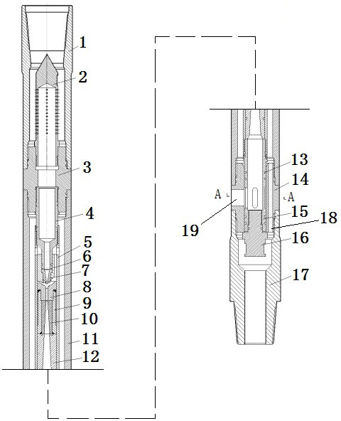
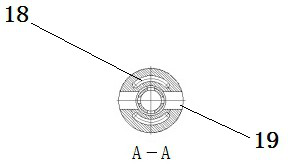
[0029] see figure 1 and figure 2 . An oil well sand flushing pump, comprising an upper joint 1, an upper sealing joint 3, an outer cylinder 11, a lower sealing joint 14, a lower joint 17, a filter cylinder 2, a high-pressure introduction joint 4, an inner sleeve 5, a nozzle 7, a nozzle support 6, Throat pipe 8, transition pipe 10, fixed sleeve 9, diffuser pipe 12, water outlet joint 15 and plug 16. The upper joint 1 is connected with the drill pipe or the oil pipe through the upper box, and the lower box of the upper joint 1 is engaged with the upper pin of the upper sealing joint 3 . The female button at the upper end of the outer cylinder 11 is engaged with the male button at the lower end of the upper sealing joint 3 , and the female button at the lower end of the outer cylinder 11 is engaged with the male button at the upper end of the lower sealing joint 14 . The female buckle at the upper end of the lower joint 17 is engaged with the male buckle at the lower end of t...

Embodiment 2

[0031] see figure 1 and figure 2. An oil well sand flushing pump, comprising an upper joint 1, an upper sealing joint 3, an outer cylinder 11, a lower sealing joint 14, a lower joint 17, a filter cylinder 2, a high-pressure introduction joint 4, an inner sleeve 5, a nozzle 7, a nozzle support 6, Throat pipe 8, transition pipe 10, fixed sleeve 9, diffuser pipe 12, water outlet joint 15 and plug 16. The upper joint 1 is connected with the drill pipe or the oil pipe through the upper box, and the lower box of the upper joint 1 is engaged with the upper pin of the upper sealing joint 3 . The female button at the upper end of the outer cylinder 11 is engaged with the male button at the lower end of the upper sealing joint 3 , and the female button at the lower end of the outer cylinder 11 is engaged with the male button at the upper end of the lower sealing joint 14 . The female buckle at the upper end of the lower joint 17 is engaged with the male buckle at the lower end of th...

Embodiment 3

[0034] see figure 1 and figure 2 . An oil well sand flushing pump, comprising an upper joint 1, an upper sealing joint 3, an outer cylinder 11, a lower sealing joint 14, a lower joint 17, a filter cylinder 2, a high-pressure introduction joint 4, an inner sleeve 5, a nozzle 7, a nozzle support 6, Throat pipe 8, transition pipe 10, fixed sleeve 9, diffuser pipe 12, water outlet joint 15 and plug 16. The upper joint 1 is connected with the drill pipe or the oil pipe through the upper box, and the lower box of the upper joint 1 is engaged with the upper pin of the upper sealing joint 3 . The female button at the upper end of the outer cylinder 11 is engaged with the male button at the lower end of the upper sealing joint 3 , and the female button at the lower end of the outer cylinder 11 is engaged with the male button at the upper end of the lower sealing joint 14 . The female buckle at the upper end of the lower joint 17 is engaged with the male buckle at the lower end of t...


PUM


Abstract

The invention discloses an oil well sand washing pump and a using method thereof. The oil well sand washing pump comprises an upper joint, an upper sealing joint, an outer cylinder, a lower sealing joint, a lower joint, a filter cartridge, a high-pressure introduction joint, an inner sleeve, a nozzle, a nozzle support, a throat pipe, a transition pipe, a fixing sleeve, a diffusion pipe, a water outlet joint and a screwed plug. The upper joint, the upper sealing joint, the outer cylinder, the lower sealing joint and the lower joint are in threaded connection in sequence; the upper sealing joint is connected with the filter cartridge upwards, and is connected with the high-pressure introduction joint inserted into the nozzle support downwards; the nozzle support with the nozzle arranged, the fixing sleeve with the throat pipe and the transition pipe inserted, and the diffusion pipe are sequentially inserted into the inner sleeve; the water outlet joint is inserted into the lower sealing joint, pushed by the diffusion pipe upwards and connected with the screwed plug downwards; and the inner sleeve is provided with a liquid inlet, and the lower sealing joint is provided with a vertical liquid through hole and a transverse liquid outlet. According to the sand washing pump, impurity blockage and part wear can be effectively avoided; the replacement and maintenance of the nozzle and the throat pipe are facilitated; the connection is firm, and components are prevented from falling off; and the suction capacity is high.

Description

technical field [0001] The invention relates to the technical field of oil field workover, in particular to an oil well sand flushing pump and a use method thereof. Background technique [0002] Venturi pump is a widely used adsorption pump that works on the principle of adsorption, and the styles and structures of the pumps vary widely according to different uses. At present, the oil well sand flushing negative pressure pump made by the Venturi principle in the petroleum industry is also one of them. However, the sand washing pumps commonly used in oilfields have the following disadvantages during use: the liquid inlet is easy to block, some parts are unreasonably connected, the structure is unstable, and the parts are easy to fall off to the bottom of the well during use, and it is not convenient to adjust the nozzle and throat. Replacement of key components, low suction capacity and other issues. [0003] Example 1: The patent titled "jet pump" (application number 20092...

Claims


Application Information

Patent Timeline
IPC IPC(8): F04F5/10F04F5/44F04F5/46E21B21/00
CPCF04F5/10F04F5/44F04F5/46E21B21/00
Inventor 吴艳华范玉斌孙经光朱庆利杨育升苏珊
Owner SINOPEC SSC
Learn More