Electric furnace flue gas waste heat utilizing method of dust collector with air exhaust barrel

A flue gas waste heat and exhaust tube technology, which is applied in furnaces, waste heat treatment, furnace components, etc., can solve the problems of high investment cost, large floor space and high resistance, and achieve low maintenance costs, reduced floor space, and reduced The effect of local drag loss

Inactive Publication Date: 2018-05-29
无锡市东优环保科技有限公司
View PDF0 Cites 0 Cited by
  • Summary
  • Abstract
  • Description
  • Claims
  • Application Information

AI Technical Summary

Problems solved by technology

[0004] When the dust collector and the exhaust tube are arranged separately, generally the fan is placed next to the dust collector, and the exhaust tube is placed next to the fan. The connecting pipes have high investment costs, large floor space, high resistance and high power consumption.

Method used


Image

  • Electric furnace flue gas waste heat utilizing method of dust collector with air exhaust barrel

Examples


Embodiment Construction

[0011] Below in conjunction with accompanying drawing, the present invention will be further described:

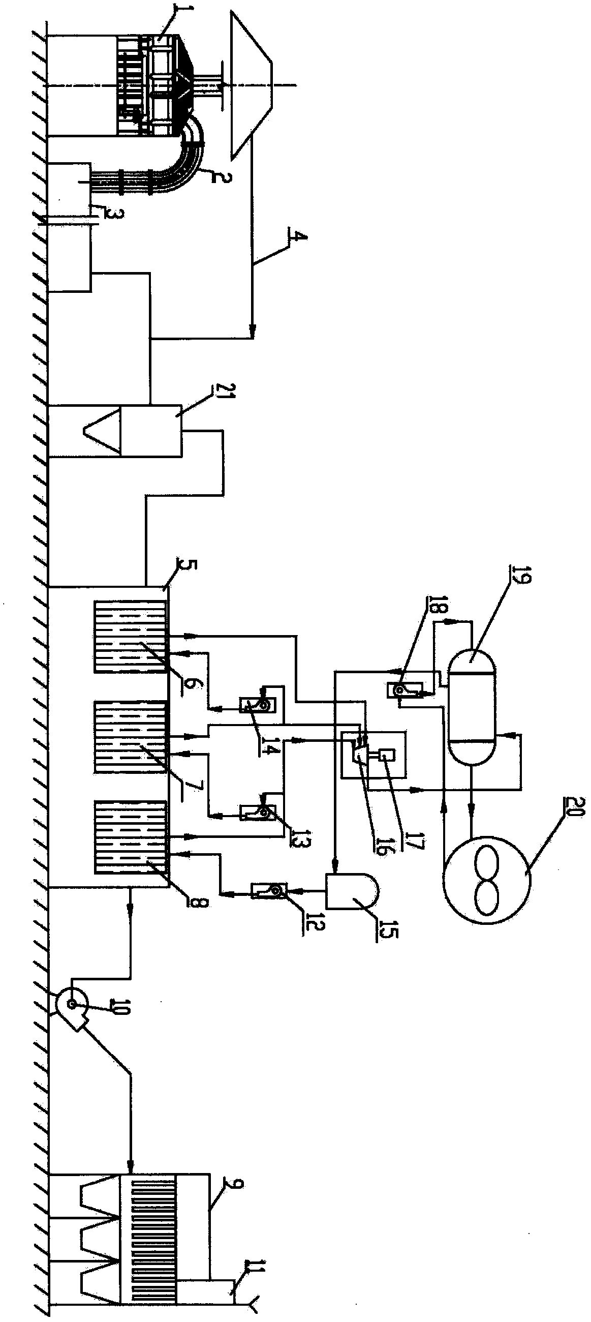
[0012] Such as figure 1 Shown: a kind of dust remover of the present invention has the electric furnace flue gas residual heat utilization method step of exhaust pipe as follows:

[0013] 50t / h steelmaking electric furnace 1 exhaust gas flow rate 18×10 4 N m 3 / h, temperature 1000℃, dust concentration 25g / Nm 3 It is discharged from the fourth hole, mixed with cold air through the water-cooled sliding sleeve 2, and enters the combustion settling chamber 3 after burning carbon monoxide gas; Mixed with cold wind, the carbon monoxide gas is eventually burned, the flue gas from the combustion settling chamber 3 is mixed with the flue gas from the exhaust pipe 4 connected above the electric furnace 1, and enters the cyclone dust collector 21 for pre-dust removal, and then enters the waste heat exchange In room 5, the high-temperature flue gas releases heat, the temperature d...


PUM


Abstract

Disclosed is an electric furnace flue gas waste heat utilizing method of a dust collector with an air exhaust barrel. The electric furnace flue gas waste heat utilizing method of the dust collector with the air exhaust barrel is characterized in that exhausted flue gas in an electric furnace is exhausted from a fourth hole, cold air is mixed into the flue gas through a water-cooled sliding sleeve,and the flue gas enters a combustion sedimentation chamber after carbon monoxide gas is burned; and the combustion sedimentation chamber has the function that the flow rate of the flue gas is decreased, large granular dust carried in the flue gas is subsided, the cold air is properly mixed into the flue gas, finally the carbon monoxide gas is burned completely, the flue gas coming out from the combustion sedimentation chamber and the flue gas coming out from an external exhaust pipeline connected to the upper portion of the electric furnace are mixed, together enter the cyclone dust collectorfor pre-dedusting, and then enter a waste heat exchanging chamber, and the high-temperature flue gas releases heat. According to the electric furnace flue gas waste heat utilizing method of the dustcollector with the air exhaust barrel, heat energy in the flue gas can be recycled to the utmost extent and is directly converted into high-grade electric energy, the heat efficiency of the method isincreased by 31%-36% compared with that of single-stage evaporation organic rankine cycle, the environmental protection effect is good, the dust collector is provided with the air exhaust barrel, thesteel consumption amount and the civil engineering investment are reduced, running power consumption is reduced, and the purpose of reducing the running cost of a dedusting system is achieved.

Description

technical field [0001] The invention relates to a method for utilizing waste heat of electric furnace flue gas with a dust collector equipped with an exhaust tube, specifically, it can maximize the recovery of heat energy in the flue gas and convert it into high-grade electric energy, and can improve the dust removal ability, belonging to the electric furnace dust removal technology field. Background technique [0002] At present, waste heat utilization facilities are commonly used: water tube waste heat boilers, regenerative waste heat boilers to recover waste heat from electric furnace flue gas, and generate saturated steam, etc. Because the flue gas temperature fluctuates sharply and the dust content is large, it is difficult for ordinary water tube waste heat boilers to be used in the waste heat recovery of flue gas from electric furnaces. At present, regenerative waste heat boilers have been successfully used in electric furnace flue gas waste heat recovery, but due to...

Claims


Application Information

Patent Timeline
Patent Type & Authority Applications(China)
IPC IPC(8): F27D17/00
CPCF27D17/004F27D17/008Y02P10/25
Inventor 周琴
Owner 无锡市东优环保科技有限公司
Why Eureka
Try Eureka