A high-pressure seepage test device
A technology of test device and overflow device, which is applied in the field of seepage, can solve the problems of being unable to meet the needs of use and limited pressure, and achieve the effect of good adaptability and convenient use
- Summary
- Abstract
- Description
- Claims
- Application Information
AI Technical Summary
Problems solved by technology
Method used
Image
Examples
Embodiment 1
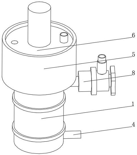
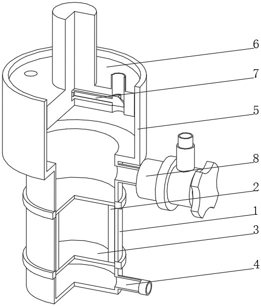
[0035] See Figure 1-3 The present invention provides a technical solution: a high pressure seepage test device, including:
[0036] Perflowing cylinder 1, the perfiolifier 1 inner wall is fixedly connected to the storage cartridge 2, the top and bottom of the storage cartridge 2 are provided with a metal thinning network 3, and the storage tube 2 is filled with a seepage medium, and the permeable tube 1 is located in the stock. The portion below the cartridge 2 communicates with the water pipe 4;
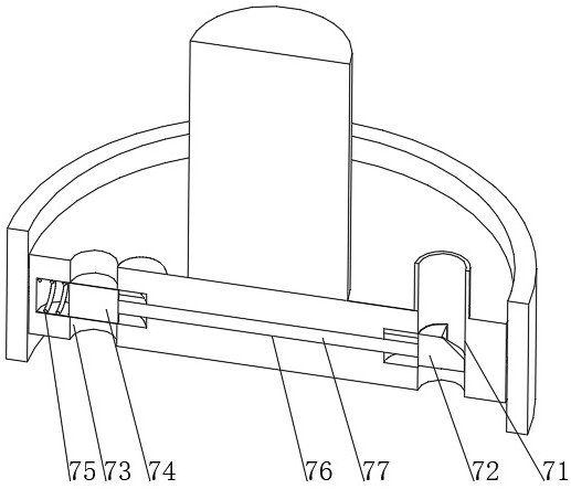
[0037] The pressurizing cylinder 5 is disposed at the top of the peri-joining cylinder 1 and communicated with the perfoamine 1, and the inner wall of the pressurizing cylinder 5 is slidably connected to the pressurized piston 6, the pressurized piston 6 is connected to the external hydraulic device, and the pressurized piston 6 is connected. Internal arrangement device 7;
[0038]Overflow device 8, the overflow device 8 is disposed on the top side of the flow tube 1, an overflow device...
Embodiment 2
[0045] See Figure 1-4 In a basic embodiment of the present invention provides a technical solution: an overflow means 8 comprises an overflow pipe 81, the overflow pipe 81 communicates at one end with a control tube 82, one end of the control tube 82 remote from the overflow pipe 81 by sealed bearings rotatably connected to the rotatable tube 83, rotation of the pipe 83 communicated with the top of the bellows 84, 83 away from one side of the control tube 82 is rotated through the tube and fixedly connected with a rotary handle 85, rotating the handle 85 extends to an end of the control tube 82 and fixedly connected with the interior rotation of the shutter 86, the shutter 86 is rotated away from the rotation of the handle 85 is slidably connected to a side of the sealing plate 87, rotation of the baffle 86 is rotated close to the top side of the handle 85 defines a communicating hole 88, the overflow pipe 81 away from the control pipe 82 one end of the flow tube 1 communicates wi...
Embodiment 3
[0048] See Figure 1-5 In a basic embodiment and the Example II embodiment the present invention provides a technical solution: a fixed seal plate 87 includes a plate 871, fixed plate 82 fixedly connected to the inner wall of the arcuate side surface 871 and the control tube, close to the fixing plate 871 is rotated baffle side by a spring 86 is connected with a pressure plate 872, fixed plate 871 and the pressing plate 872 are set to a semicircular pressing plate 872 away from the side of the fixed plate 871 is fixedly connected with a sealing strip 873, 871 fixed to the side plate defines a hollow bore, a sealing plate 87, when the overflow device 8 in a sealed state, the water inside the flow tube 1 through the overflow pipe 81 into the interior of the control tube 82, tube 82 and control 87 generates the internal pressure of the sealing plate , the pressure acting through the hollows 872 on the pressure plate, the pressure plate 872 and may seal 873 pressed against the bezel 86...
PUM
 Abstract
Description
Claims
Application Information
 - R&D
- Intellectual Property
- Life Sciences
- Materials
- Tech Scout
- Unparalleled Data Quality
- Higher Quality Content
- 60% Fewer Hallucinations
Browse by: Latest US Patents, China's latest patents, Technical Efficacy Thesaurus, Application Domain, Technology Topic, Popular Technical Reports.
© 2025 PatSnap. All rights reserved.Legal|Privacy policy|Modern Slavery Act Transparency Statement|Sitemap|About US| Contact US: help@patsnap.com


