Converter circuit, corresponding device and method

A circuit and logic circuit technology, applied in the field of converter circuits, can solve the problems of hysteresis controller differential steady-state PWM frequency, slow transient response, etc., to achieve enhanced transient response, wide output range, and improved inductor current conversion rate Effect

Pending Publication Date: 2021-10-12
STMICROELECTRONICS SRL
View PDF5 Cites 0 Cited by
  • Summary
  • Abstract
  • Description
  • Claims
  • Application Information

AI Technical Summary

Problems solved by technology

[0014] Potentially slower transient response due to synchronous operation
[0015] Also, the operation of a hysteretic controller may exhibit poor steady-state PWM frequency behavior as the input and output voltages change in

Method used


Image

  • Converter circuit, corresponding device and method
  • Converter circuit, corresponding device and method
  • Converter circuit, corresponding device and method

Examples


Embodiment Construction

[0038] In the ensuing description, one or more specific details are set forth in order to provide an in-depth understanding of examples of the described embodiments. Embodiments may be obtained without one or more of the specific details, or with other methods, components, materials, etc. In other instances, known structures, materials, or operations are not shown or described in detail so as not to obscure aspects of the embodiments.

[0039] References to "an embodiment" or "one embodiment" in the context of the present description are intended to indicate that a particular configuration, structure or characteristic described with respect to the embodiment is included in at least one embodiment. Thus, phrases such as "in an embodiment" or "in one embodiment," which may appear at one or more points in the description, are not necessarily referring to the same embodiment.

[0040] Furthermore, particular configurations, structures or characteristics may be combined in any sui...


PUM


Abstract

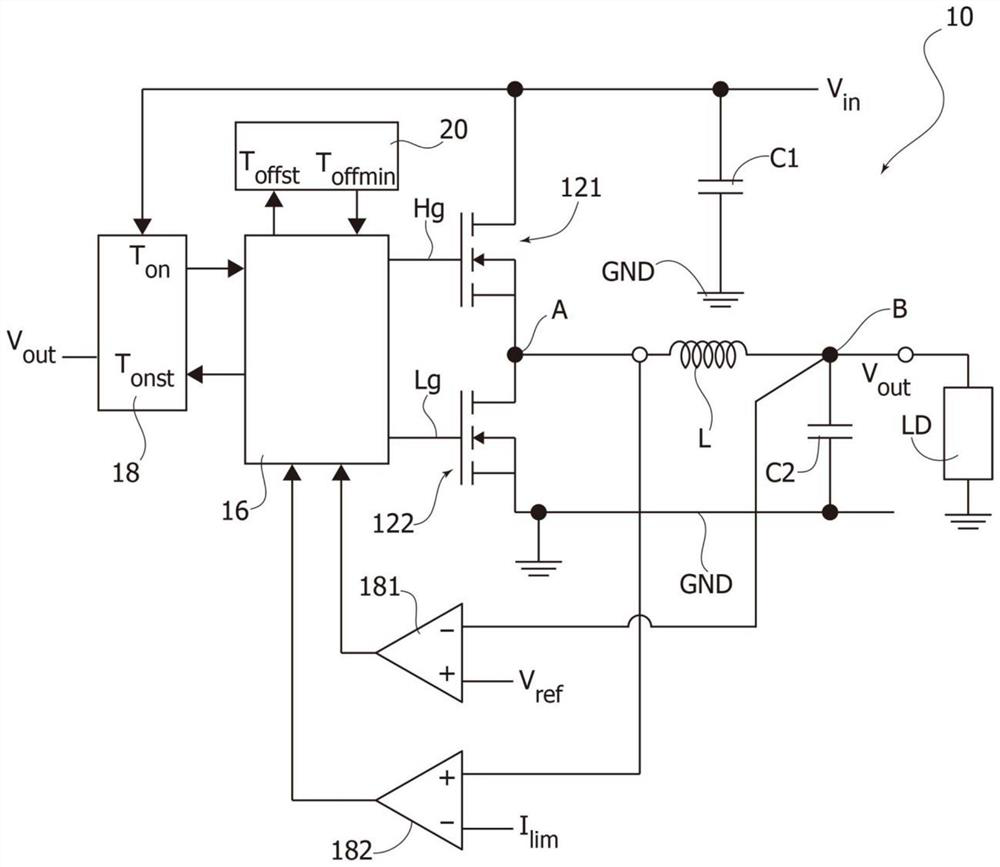
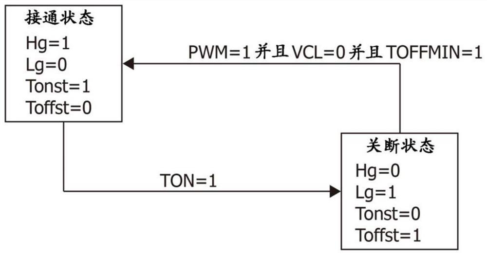
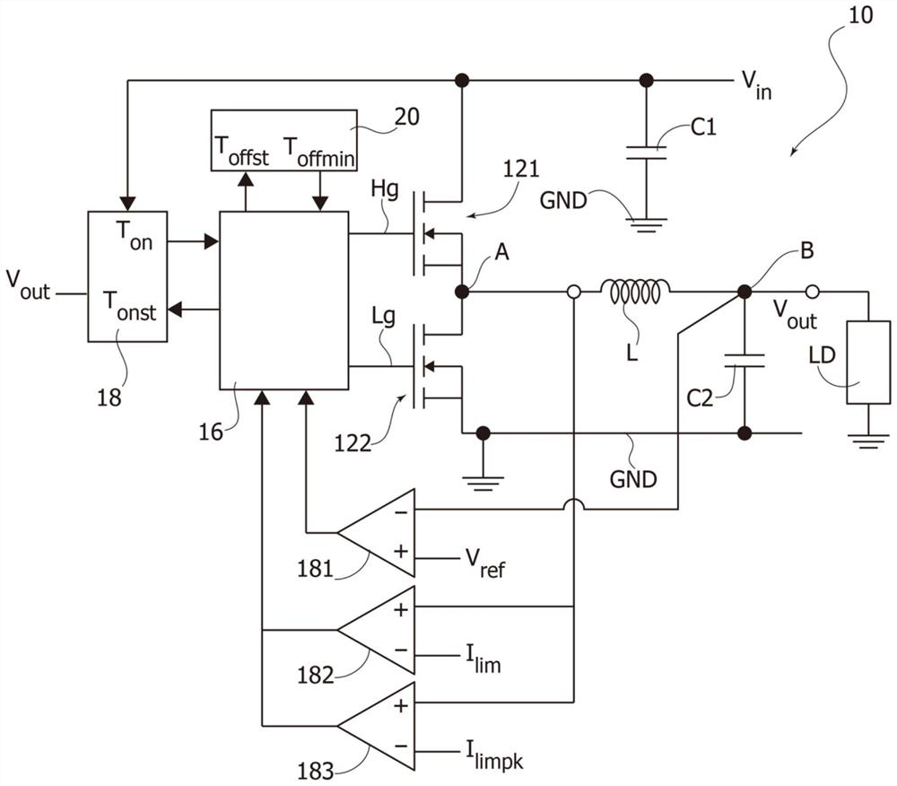
The embodiment of the invention relates to a converter circuit, a corresponding device and a method. The converter circuit includes a half-bridge power circuit having first and second switches between the input node and the current node and between the current node and ground, respectively. The inductor is coupled between the current node and the output node. A logic control circuitry is configured to switch the first and second switches to a current recirculation state and a current charging state. The logic circuitry is configured to switch the switch from the current recirculation state to the current charging state as a result of the voltage indicator signal from the output voltage comparator being asserted while initiating an on-time counter signal having an expiration value, and switches the switch from the current charging state to the current recirculation state as a result of a combination of the on-time counter signal having reached its expiration value with the voltage indicator signal from the voltage comparator being de-asserted.

Description

technical field [0001] This description refers to converter circuits. One or more embodiments may be implemented in a wide variety of devices such as, for example, wireless battery chargers, USB controllers, or lithium-ion (Li-ion) battery powered devices. Background technique [0002] Converter circuits such as so-called "buck" DC-DC power converters are widely used for power conversion in many applications. [0003] Buck DC-DC converters with constant "on" time (on time) are widely used due to high responsiveness, reliability and simple design. [0004] These converters are examples of conventional converter circuits where factors such as maximum duty cycle and inductor charging slew rate may be limited by a minimum "off" time (off time). [0005] Such conventional converter circuits may consider various modes of operation, such as (synchronous) peak current mode, voltage mode (PWM) or hysteretic controller operation. [0006] In peak current mode, the on-time is starte...

Claims


Application Information

Patent Timeline
Patent Type & Authority Applications(China)
IPC IPC(8): H02M3/158H02M1/088
CPCH02M3/158H02M1/088H02M1/0022H02M1/0003Y02B70/10
Inventor A·马里亚尼
Owner STMICROELECTRONICS SRL
Why Eureka
Try Eureka