A forming mold outer arc chamfering structure

A technology of chamfering structure and forming molds, which is applied in the direction of manufacturing tools, large fixed members, and other manufacturing equipment/tools, etc., and can solve the problem of reducing input costs, low automatic integration capabilities, and no ability to synchronously process chamfering and grinding and other issues to achieve the effect of reducing input costs and reducing manual assistance

Active Publication Date: 2022-06-24
宏辉磁电科技(安徽)有限公司
View PDF10 Cites 0 Cited by
  • Summary
  • Abstract
  • Description
  • Claims
  • Application Information

AI Technical Summary

Problems solved by technology

[0005] The purpose of the present invention is to provide a forming mold outer arc chamfering structure to solve the problem that the existing device itself proposed in the background technology has low automatic integration ability and does not have the ability to synchronously process chamfering and grinding. By increasing the workmanship on the equipment Structure, adjust the contact distance between different action areas and workpieces, so that after the chamfering is formed, the burrs and other uneven structures on it can be processed in time and effectively, without the need for back and forth replacement between devices, reducing input costs

Method used


Image

  • A forming mold outer arc chamfering structure
  • A forming mold outer arc chamfering structure
  • A forming mold outer arc chamfering structure

Examples


Embodiment Construction

[0028] The technical solutions in the embodiments of the present invention will be clearly and completely described below with reference to the accompanying drawings in the embodiments of the present invention. Obviously, the described implementation regulations are only a part of the embodiments of the present invention, rather than all the embodiments. Based on the embodiments of the present invention, all other embodiments obtained by those of ordinary skill in the art without creative efforts shall fall within the protection scope of the present invention.

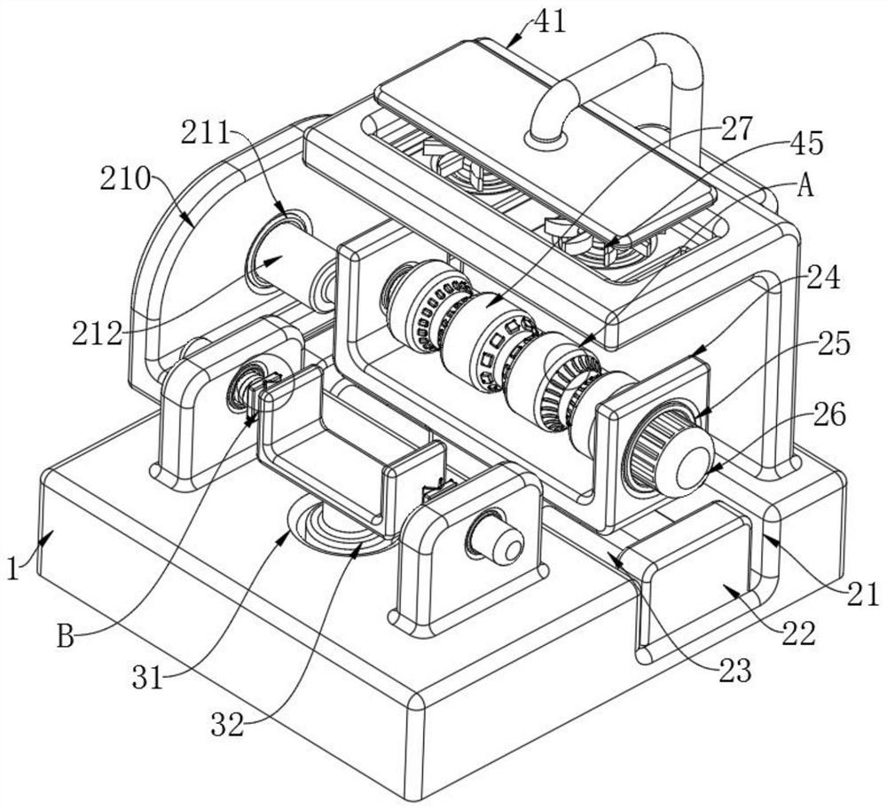
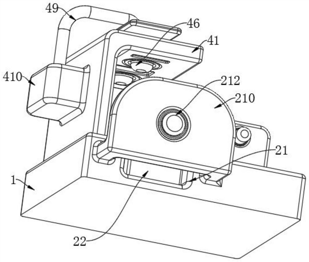
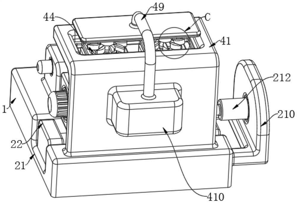
[0029] see Figure 1-6 As shown, the present invention provides a technical solution: an outer arc chamfering structure of a forming mold, comprising: a bottom plate 1, and a correction grinding mechanism 2, a workpiece adjustment mechanism 3 and a waste collection mechanism 4 are fixedly installed on the top of the bottom plate 1 respectively.

[0030] according to Figure 1-4 As shown, the correction grinding mechan...


PUM


Abstract

The invention discloses an outer arc chamfering structure of a forming mold, comprising: a base plate, the top of the base plate is respectively fixed with a correction and grinding mechanism, a workpiece adjustment mechanism and a waste material collection mechanism, which are converted to the inside of the second ring groove for processing There are burrs and some uneven structures in the rear chamfering part, which is in contact with the rough grinding block in the second ring groove. After a period of processing, the metal mounting bracket is moved again and changed to the third ring groove. Inside, the chamfering of the workpiece after two treatments is contacted with the fine-faced grinding block in the third ring groove, and the final treatment is carried out. Through the above conditions, the chamfering and post-grinding of the existing device cannot be processed synchronously. The effect is to adjust the contact distance between different action areas and workpieces, so that after the chamfering is formed, the burrs and other uneven structures on it can be dealt with effectively in time, without the need for back and forth replacement between devices, reducing input costs.

Description

technical field [0001] The invention relates to the technical field of chamfering equipment, in particular to an outer arc chamfering structure of a forming die. Background technique [0002] Generally, the function of chamfering is to remove burrs and make them beautiful. However, for the chamfering specified in the drawing, it is generally a requirement of the installation process, such as the installation guide of the bearing, and some arc chamfers (or arc transitions) can also reduce stress concentration and strengthen shafts. The effect of the strength of the part. In addition, assembly can be facilitated, generally before the end of processing. On agricultural machinery parts, especially the end faces of round fittings and round holes are often processed into chamfers of about 45°. These chamfers have various functions, and must be carefully checked during maintenance operations and fully utilized, otherwise it will bring many difficulties to agricultural machinery ...

Claims


Application Information

Patent Timeline
Patent Type & Authority Patents(China)
IPC IPC(8): B23P23/04B23Q1/25B23Q11/00
CPCB23P23/04B23Q1/25B23Q11/0046B23Q11/0067
Inventor 陈锦华
Owner 宏辉磁电科技(安徽)有限公司
Why Eureka
Try Eureka