
Carbon fiber winding machine

A winding machine and carbon fiber technology, applied in the field of carbon fiber winding machines, can solve the problems of inability to perform programming operations, increasing the production cost of the winding machine, and high technical requirements

Pending Publication Date: 2021-10-15
WEIHAI GERNUMAN AUTOMATION TECH CO LTD
View PDF5 Cites 2 Cited by
  • Summary
  • Abstract
  • Description
  • Claims
  • Application Information

AI Technical Summary

Problems solved by technology

[0003] In the prior art, the winding layout of the fiber winding is controlled electronically. This method needs to increase various control circuits, increase the production cost of the winding machine, and when it is necessary to change the winding layout, special equipment is required. Engineers carry out control programming. This method increases the cost of carbon fiber winding for convenience, and has high technical requirements. Half of the personnel cannot perform programming operations, which is not conducive to the promotion of winding machines. Therefore, a simple controllable fiber is designed. Filament winding machine with winding layout is particularly important
[0004] In summary, there are obviously inconveniences and defects in the actual use of the existing technology, so it is necessary to improve

Method used

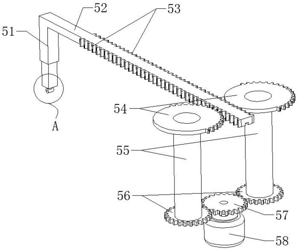
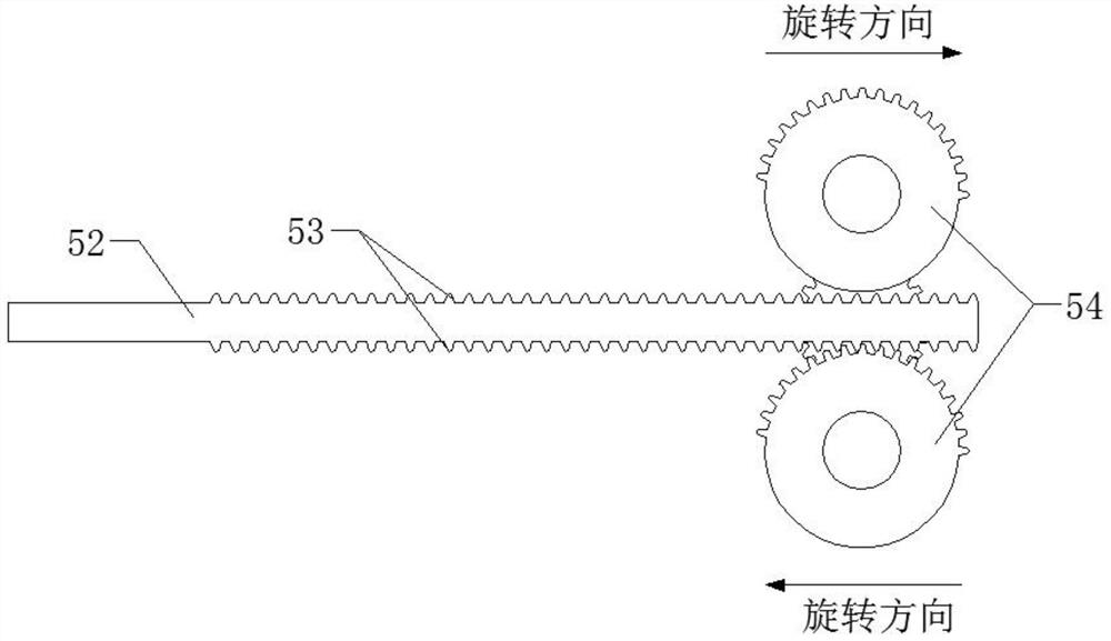

Image

  • Carbon fiber winding machine
  • Carbon fiber winding machine
  • Carbon fiber winding machine

Examples


Embodiment Construction

[0020] In order to make the objectives, technical solutions and advantages of the present invention clearer, the present invention will be described in further detail below in conjunction with the accompanying drawings and embodiments. It should be understood that the specific embodiments described here are only used to explain the present invention and are not intended to limit the invention.

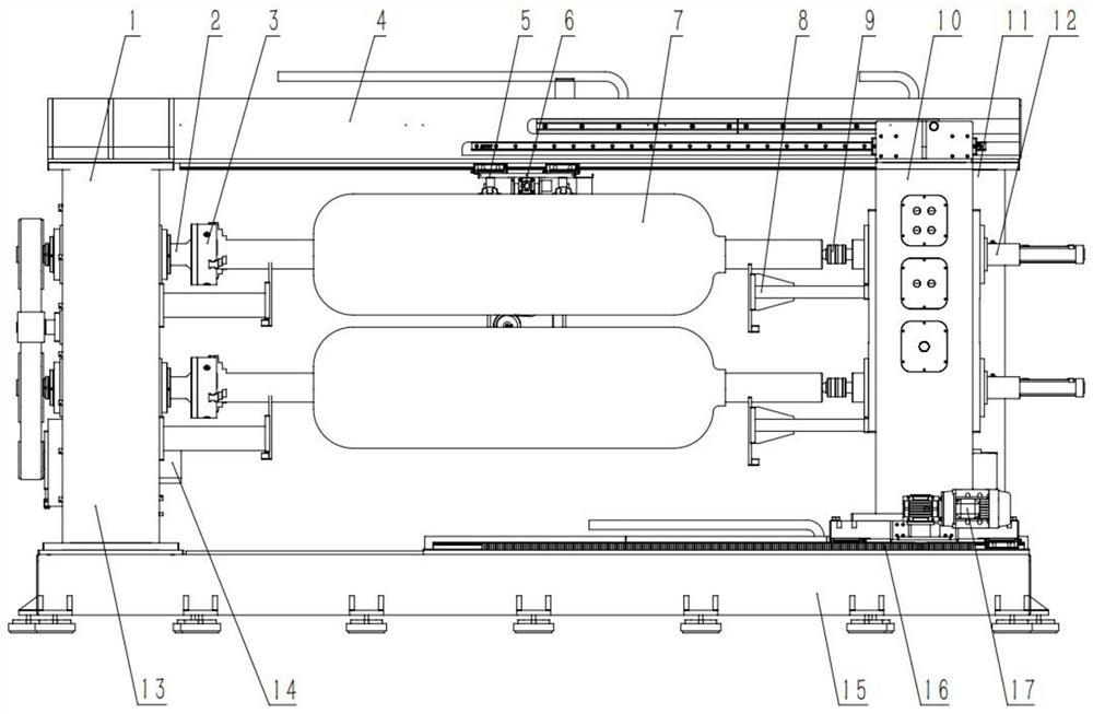
[0021] see figure 1 , the present invention provides a carbon fiber winding machine, the carbon fiber winding machine includes a main frame body 1, a feeding mechanism 5 and a drive assembly, the main frame body 1 includes a base 15, a fixed column 13, a movable column 10 and a beam 4, The crossbeam 4 is fixed on the top of the movable column 10 and the fixed column 13, the crossbeam 4 spans between the two columns, and the crossbeam 4 and the movable column 10 can move to ensure that the movable column 10 can translate normally , the fixed column 13 is affixed to the top of the base ...


PUM


Abstract

The invention is applicable to the technical field of fiber winding equipment, and provides a carbon fiber winding machine. The carbon fiber winding machine comprises a main frame body, a feeding mechanism and a driving assembly; the main frame body comprises a base, a fixed stand column, a movable stand column and a cross beam, the cross beam is fixedly arranged at the top of the movable stand column, a chuck is arranged in the middle of the fixed stand column, and a winding mold is fixedly connected between the chuck and the movable stand column; the feeding mechanism comprises a sliding rod connected to the cross beam in a sliding manner, a driving motor for driving the sliding rod to slide in a reciprocating manner and a material distributing piece movably connected to the top of the sliding rod; and the driving assembly comprises a translation rack fixed to the top of the base and a sliding motor, the bottom of the movable stand column cooperates with the translation rack, and the sliding motor drives the movable stand column to move on the translation rack. Therefore, by optimizing the feeding mechanism and through a simple transmission mode, control over the simple transmission speed and control over the layout mode during fiber winding are achieved, and the technical effects that operation is simple and the manufacturing cost is low are achieved.

Description

technical field [0001] The invention relates to the technical field of fiber winding equipment, in particular to a carbon fiber winding machine. Background technique [0002] With the localization of carbon fiber materials, carbon fiber products are becoming more and more popular. Carbon fiber tubes are a widely used product. Carbon fiber tubes have the characteristics of high strength, long life, corrosion resistance, light weight, low density, etc., and have high specific mold , fatigue resistance, creep resistance, high temperature resistance, corrosion resistance, wear resistance, etc.; the strength of carbon fiber tubes is 6-12 times that of steel, which can reach more than 3000Mpa, and the density is less than 1 / 4 of steel. The strength and safety of the gas cylinder can be increased by carbon fiber winding, which is widely used. [0003] In the prior art, the winding layout of the fiber winding is controlled electronically. This method needs to increase various contr...

Claims


Application Information

Patent Timeline
IPC IPC(8): B29C53/66B29C53/80
CPCB29C53/66B29C53/8016
Inventor 朱勇代吉祥王黎明
Owner WEIHAI GERNUMAN AUTOMATION TECH CO LTD
Learn More