Arrangement and installation method and structure of tail water surge shaft gate and opening and closing equipment

A water surge well and installation structure technology, applied in hydropower, water conservancy projects, hydropower stations, etc., can solve the problems of increased investment, overflow, damage, etc., and achieve the effect of saving investment and locking the gate firmly

Active Publication Date: 2021-10-15
CHINA POWER CONSRTUCTION GRP GUIYANG SURVEY & DESIGN INST CO LTD
View PDF15 Cites 0 Cited by
  • Summary
  • Abstract
  • Description
  • Claims
  • Application Information

AI Technical Summary

Problems solved by technology

[0002] For tailwater surge wells with multiple units, in order to reduce the impact of water hammer caused by load shedding of a single unit on the power generation of other units, generally more than two units of tail water surge wells are usually separated by rock ridges. And the setting height of the rock ridge should be higher than the highest surge water level, otherwise the gushing water will overflow the surge well and cause damage to the facilities around the tailwater surge well; The gates of the tail water surge wells adopt the "one door, one machine" arrangement operated by a fixed winch, and there is a problem of excessive investment in metal structures; if multiple tail water surge wells are used to share the tail water pressure regulation According to the layout of the well gate, the gate of the tailwater surge well needs to be operated by mobile hoisting equipment, because the bottom of the gate of the tailwater surge well must be higher than the top of the rock ridge to meet the requirements of lifting the gate to all the gates through the mobile hoisting equipment In the gate slot, this will result in a higher height of the tailwater surge well cavern, which will increase investment; in addition, the traditional tailwater surge well gate is directly locked on the inspection platform at the top of the gate slot, because the height of the platform is higher than that of the highest surge well. The wave water level is relatively low, and it is easy to overturn and cause damage under the impact of repeated fluctuations in the gushing water; in addition, the traditional method of setting rock anchor hooks and installing gates and hoisting equipment through temporary lifting equipment for tailwater surge tanks is relatively heavy. The gates and hoisting equipment, rock anchor hooks bear limited loads, which usually do not meet the requirements. Therefore, the existing technology is still not perfect and needs to be further improved.

Method used


Image

  • Arrangement and installation method and structure of tail water surge shaft gate and opening and closing equipment
  • Arrangement and installation method and structure of tail water surge shaft gate and opening and closing equipment
  • Arrangement and installation method and structure of tail water surge shaft gate and opening and closing equipment

Examples


Embodiment 1

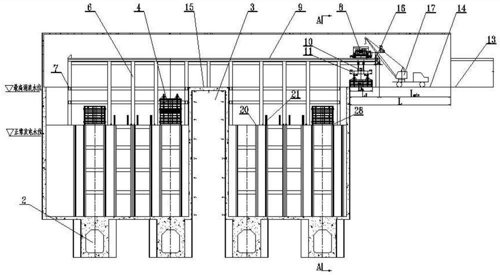
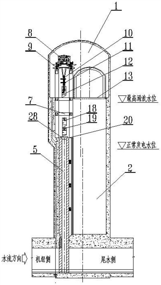
[0050] as attached figure 1 , figure 2 , Figure 7-10 As shown, in this embodiment, the tail water surge chamber 1 is composed of two independent tail water surge wells 2, and adjacent independent tail water surge wells 2 are separated by rock ridges 3 . Each independent tail water surge well 2 is provided with two tail water surge well gates 4, and the centerlines of the gate grooves 5 of all tail water surge well gates 4 are arranged on the same straight line. The connecting beam 7 is canceled in the middle of the bent frame 6 of the killing well 4 along the water flow direction; the gate 4 of the tailwater surge well is operated by a trolley 8; 1 >Trolley lifting head 10 upper limit size h t + The distance h between the centers of the upper and lower hanging heads of the hydraulic grab beam 11 y + Single door leaf 12 maximum height h when installed max ; Tail water surge well gate 4 and trolley 8 are transported to installation platform 14 through traffic hole 13.

...

Embodiment 2

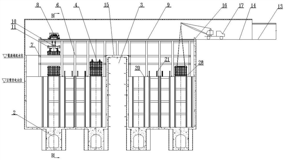
[0054] as attached image 3 , Figure 4 , Figure 7-10 As shown, in this embodiment, the tail water surge chamber 1 is composed of two independent tail water surge wells 2, and adjacent independent tail water surge wells 2 are separated by rock ridges 3 . Each independent tail water surge well 2 is provided with two tail water surge well gates 4, and the centerlines of the gate grooves 5 of all tail water surge well gates 4 are arranged on the same straight line. The middle part of the bent frame 6 of the killing well 4 is along the water flow direction, and the connecting beam 7 is cancelled; the gate 4 of the tailwater surge well is operated by a trolley 8; 1 >Trolley lifting head 10 upper limit size h t + The distance h between the centers of the upper and lower hanging heads of the hydraulic grab beam 11 y + Single door leaf 12 maximum height h when installed max ; Tail water surge well gate 4 and trolley 8 are transported to installation platform 14 through traffic h...

Embodiment 3

[0057] as attached Figure 5-10 As shown, in this embodiment, the tail water surge chamber 1 is composed of two independent tail water surge wells 2, and adjacent independent tail water surge wells 2 are separated by rock ridges 3 . Each independent tail water surge well 2 is provided with two tail water surge well gates 4, and the centerlines of the gate grooves 5 of all tail water surge well gates 4 are arranged on the same straight line. The connecting beam 7 is canceled in the middle of the bent frame 6 of the killing well 4 along the flow direction; the gate 2 of the tailwater surge well is operated by the portal crane 29, and the elevation of the rail platform 30 of the portal crane and the elevation of the bottom of the traffic tunnel 13 are the same as the elevation of the top platform 15 of the rock ridge. Lift H on gantry crane 29 rails gs >The distance h between the centers of the upper and lower lifting heads of the hydraulic grab beam 11 y + Single door leaf 12 ...


PUM


Abstract

The invention discloses an arrangement and installation method and structure of a tail water surge shaft gate and opening and closing equipment. According to the method, a tail water surge chamber is designed into two or more independent tail water surge shafts, adjacent independent tail water surge shafts are separated by a rock ridge, and the top elevation of the rock ridge is slightly higher than the highest surge water level of the tail water surge shafts; at least one tail water surge shaft gate is arranged on each independent tail water surge shaft, and gate groove center lines of all the tail water surge shaft gates are arranged on the same straight line; a connecting beam in the middle of a framed bent of each independent tail water surge shaft is omitted in the water flow direction; the opening and closing equipment is connected to the gates through grabbing beams; the elevation height from the center of a grabbing beam lower hanging head to the top of the rock ridge is larger than the maximum height of a single-section gate leaf of the gate; and the gate is stored and fixed through a beam column combined type locking device or a gate storage groove arranged on a maintenance platform. According to the arrangement and installation method and structure, the tail water surge shaft gate is operated through the movable opening and closing device, and the overhaul requirement of a power station can be met without the rock ridge.

Description

technical field [0001] The invention relates to an arrangement and installation method and structure of a tailwater surge well gate and hoisting equipment, and belongs to the technical field of metal structures of hydropower and water conservancy projects. Background technique [0002] For tailwater surge wells with multiple units, in order to reduce the impact of water hammer caused by load shedding of a single unit on the power generation of other units, generally more than two units of tail water surge wells are usually separated by rock ridges. And the setting height of the rock ridge should be higher than the highest surge water level, otherwise the gushing water will overflow the surge well and cause damage to the facilities around the tailwater surge well; The gates of the tail water surge wells adopt the "one door, one machine" arrangement operated by a fixed winch, and there is a problem of excessive investment in metal structures; if multiple tail water surge wells...

Claims


Application Information

Patent Timeline
Patent Type & Authority Applications(China)
IPC IPC(8): E02B9/00E02B7/36E02B7/26E02B8/04
CPCE02B9/00E02B7/36E02B7/26E02B8/045Y02E10/20
Inventor 王兴恩申显柱
Owner CHINA POWER CONSRTUCTION GRP GUIYANG SURVEY & DESIGN INST CO LTD
Why Eureka
Try Eureka