Fiber laser on-line monitoring system

A monitoring system and fiber laser technology, applied in optical instrument testing, measuring devices, testing optical performance and other directions, can solve the problems of poor protection effect of monitoring equipment, inconvenient coupling of optical fibers for collection and storage, and lack of flexible portability of monitoring equipment, etc. The effect of increasing the anti-slip effect

Inactive Publication Date: 2021-10-15
睿贸恒诚山东科技发展有限责任公司
View PDF6 Cites 0 Cited by
  • Summary
  • Abstract
  • Description
  • Claims
  • Application Information

AI Technical Summary

Problems solved by technology

[0005] In order to solve the above technical problems, the present invention provides an online fiber laser monitoring system to solve the problem that the existing fiber laser online monitoring system does not have the flexibility to carry the monitoring equipment according to the needs, and the protection effect on the monitoring equipment is poor and ineffective. Convenient pair-coupled fiber collection and storage issues

Method used


Image

  • Fiber laser on-line monitoring system
  • Fiber laser on-line monitoring system
  • Fiber laser on-line monitoring system

Examples


Embodiment

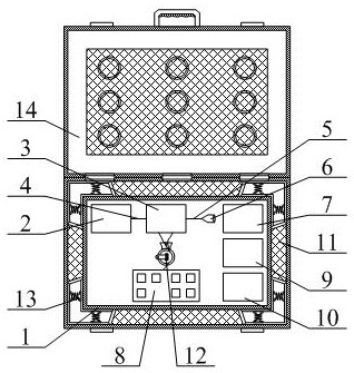
[0038] as attached figure 1 And attached Figure 4As shown, the present invention provides a fiber laser online monitoring system, including an installation frame 1, a laser generating component 2, a fiber sampler 3, a left transmission fiber 4, a right transmission fiber 5, a laser output head 6, and an end detection unit 7. The middle detection unit 8, the signal processing circuit 9 and the data processing and acquisition unit 10, the installation frame 1 is placed in the middle position inside the storage frame 141, and it is convenient to remove the installation frame 1 from the storage frame 141 according to the requirement during use , and then it is convenient to maintain the parts on the installation frame 1; the laser generating part 2, the fiber sampler 3 and the end detection unit 7 are installed on the upper side of the installation frame 1 in sequence from left to right; the left The side transmission fiber 4 is plugged in on the left side of the fiber sampler 3...


PUM


Abstract

The invention provides an optical fiber laser on-line monitoring system. The system comprises a mounting frame, a laser generating part, an optical fiber sampler, a left side transmission optical fiber, a right side transmission optical fiber, a laser output head, an end detection unit, a middle detection unit, a signal processing circuit and a data processing and collecting unit, wherein the laser generating part, the optical fiber sampler and the end detection unit are sequentially mounted on the upper side of the mounting frame from left to right; the left side transmission optical fiber is inserted into the left side of the optical fiber sampler, and meanwhile, the left side transmission optical fiber is in contact with the laser generating component; and the right side transmission optical fiber is inserted into the right side of the optical fiber sampler. The lifting handle is installed on the upper middle portion of the protective cover through screws so that a user can conveniently hold the lifting handle to lift the protective cover during use; and the damping spring is arranged between the inner side L-shaped plate and the outer side L-shaped plate so that a damping protection effect can be achieved on the monitoring equipment when the monitoring equipment is lifted during use.

Description

technical field [0001] The invention belongs to the technical field of fiber laser monitoring, and in particular relates to an online monitoring system of fiber laser. Background technique [0002] Optical fiber, short for optical fiber, is a fiber made of glass or plastic that acts as a means of light transmission. The transmission principle is "total reflection of light". Fiber laser (FiberLaser) refers to a laser that uses a rare earth-doped glass fiber as a gain medium. Fiber lasers can be developed on the basis of fiber amplifiers: under the action of pump light, high power density is easily formed in the fiber, resulting in laser operation. The laser energy level of the material is "particle number inversion", and when properly added to the positive feedback loop (to form a resonant cavity), the laser oscillation output can be formed. [0003] However, the existing fiber laser online monitoring system does not have the flexibility to carry the monitoring equipment ac...

Claims


Application Information

Patent Timeline
Patent Type & Authority Applications(China)
IPC IPC(8): G01M11/02
CPCG01M11/02G01M11/0207
Inventor 苏宜刚
Owner 睿贸恒诚山东科技发展有限责任公司
Why Eureka
Try Eureka