Biliary stent with a positioning structure for hepatobiliary pancreatic surgery

A technology for positioning structures and biliary tracts, applied in the direction of stents, can solve problems such as biliary tract strangulation, sliding of biliary stents, infection, etc., and achieve the effect of reducing the possibility of loosening, ensuring stable placement, and ensuring stability

Pending Publication Date: 2021-10-19
JILIN UNIV FIRST HOSPITAL
View PDF0 Cites 0 Cited by
  • Summary
  • Abstract
  • Description
  • Claims
  • Application Information

AI Technical Summary

Problems solved by technology

[0004] The purpose of the present invention is to provide a biliary tract stent with a positioning structure for hepatobiliary and pancreatic surgery, to solve the problem that the existing biliary tract stent proposed in the above background technology is a braided mesh stent made of alloy to place it in the biliary tract On the inner wall of the biliary tract, use its biliary stent to support the inner wall of the biliary tract to ensure that the inner cavity of the biliary tract remains unobstructed, so that it can generate a continuous and soft radial expansion force, which acts on the inner wall of the biliary tract to restore the patency of the narrowed part, but the biliary tract Under long-term use of the stent, it will cause strangulation marks on the inner wall of the biliary tract, and even cause damage to the inner wall of the biliary tract, causing the danger of infection. It needs to be replaced regularly, and for some special biliary tracts, the biliary stent is prone to appear. Sliding phenomenon, and when the biliary stent works normally, bile backflow is prone to occur, thus affecting the internal circulation system of the whole human body

Method used


Image

  • Biliary stent with a positioning structure for hepatobiliary pancreatic surgery
  • Biliary stent with a positioning structure for hepatobiliary pancreatic surgery
  • Biliary stent with a positioning structure for hepatobiliary pancreatic surgery

Examples


Embodiment Construction

[0026] The following will clearly and completely describe the technical solutions in the embodiments of the present invention with reference to the accompanying drawings in the embodiments of the present invention. Obviously, the described embodiments are only some, not all, embodiments of the present invention. Based on the embodiments of the present invention, all other embodiments obtained by persons of ordinary skill in the art without making creative efforts belong to the protection scope of the present invention.

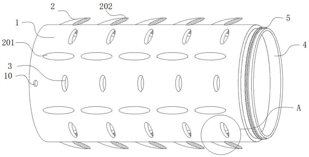
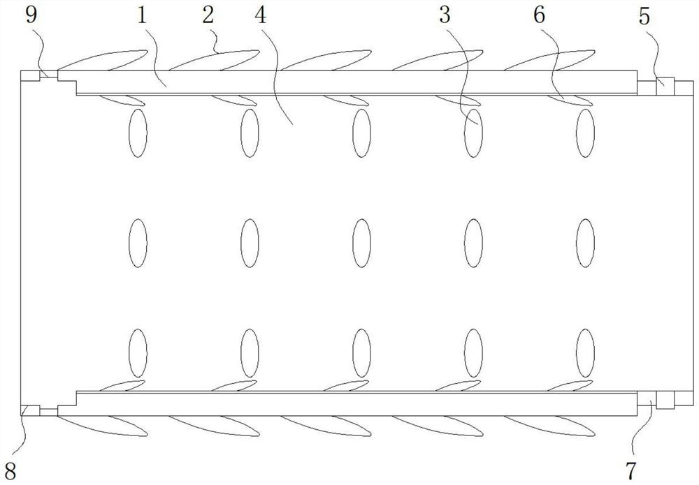
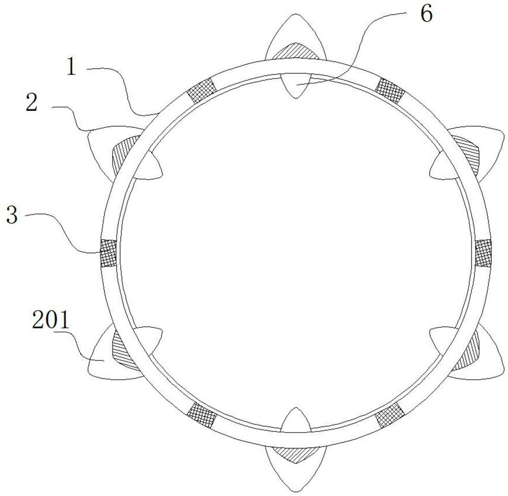
[0027] see Figure 1-5 , the present invention provides a technical solution: a biliary stent with a positioning structure for hepatobiliary and pancreatic surgery, including a biliary stent main body 1, a limit mechanism 2, an air hole 3, a stent inner wall groove 4, a snapping belt 5, and a stop valve 6 , connecting the outer wall 7, the fitting groove 8, the belt groove 9 and the clamping hole 10, the two sides of the outer wall of the biliary stent main bo...


PUM


Abstract

The invention relates to a biliary stent with a positioning structure for hepatobiliary pancreatic surgery, which comprises a biliary stent body and a limiting mechanism, clamping holes are formed in two sides of the outer wall of the biliary stent body, the limiting mechanism is arranged on the periphery of the outer wall of the biliary stent body, air holes are formed in the periphery of the outer wall of the biliary stent body, A connecting outer wall is arranged on one side of the outer wall of the biliary tract stent body, compared with the prior art, the biliary tract stent has the advantages that the barbs serve as a main structure of a limiting mechanism of the biliary tract stent, the inclined barbs face towards one side, the biliary tract stent body is clamped on the inner wall of the biliary tract through the petal shapes of the inclined barbs, the biliary tract stent body is fixed, thus to prevent the biliary stent body from loosening in the using process, the arc grooves are formed in the inner sides of the inclined barbs, the smoothness of the surface of the biliary stent body can be guaranteed through the arc grooves, abrasion of the inclined barbs to the inner wall of the biliary tract is reduced, the completeness of the biliary tract is guaranteed, and the biliary tract wall cannot be damaged.

Description

technical field [0001] The invention relates to the technical field of hepatobiliary and pancreatic surgery, in particular to a biliary stent with a positioning structure for hepatobiliary and pancreatic surgery. Background technique [0002] Biliary tract stent is a technical solution widely used in medical undertakings, especially for hepatobiliary and pancreatic surgery, it can effectively relieve the condition of patients with malignant biliary tract obstruction. It is the best preferred method, with less trauma and fewer complications. The installation of biliary stents can quickly relieve biliary obstruction, reduce biliary pressure, and unobstructed drainage, so that the patient's condition can be relieved quickly, infection can be controlled, and bile duct removal can be achieved. With the assistance of the biliary tract stent, it can perform normal human circulation operations. It is also possible to choose different types of biliary tract stent tubes according to d...

Claims


Application Information

Patent Timeline
IPC IPC(8): A61F2/848A61F2/90
CPCA61F2/848A61F2/90A61F2002/8483
Inventor 叶军锋王中峰王崇
Owner JILIN UNIV FIRST HOSPITAL
Why Eureka
Try Eureka