Eureka AIR delivers breakthrough ideas for toughest innovation challenges, trusted by R&D personnel around the world.

Efficient welding equipment based on high-power laser flight welding

A welding equipment and high-power technology, which is applied in the direction of laser welding equipment, welding equipment, welding equipment, etc., can solve the problems of affecting clamping stability, affecting processing or use, and cumbersome operation, so as to improve welding effect and prevent pinching Effects of workpieces and simplification of operation steps

Active Publication Date: 2021-10-19
苏州大鑫华激光科技有限公司
View PDF13 Cites 0 Cited by
  • Summary
  • Abstract
  • Description
  • Claims
  • Application Information

AI Technical Summary

Problems solved by technology

[0003]1. When welding plate workpieces, it is fixed by manual fastening, which is cumbersome to operate; moreover, it cannot adjust the angle between the two plates , unable to adapt to the welding work between plates with different angles, and has great limitations;
[0004]2. Before welding the plates, the welding area needs to be manually cleaned, which is not only inefficient, but also incomplete, leaving debris in the welding area, resulting in There are cracks in the welding, which affects the welding effect; moreover, there is no device to absorb and purify the welding fume, which causes the welding fume to directly diffuse into the environment, pollute the air, and have poor environmental protection;
[0005]3. There is no component to clean the clamping device, so that many debris remains on the clamping surface of different workpieces clamped many times, which not only affects the clamping Stability, at the same time, it is very easy to pinch the surface of the workpiece, which will affect the subsequent processing or use

Method used


Image

  • Efficient welding equipment based on high-power laser flight welding
  • Efficient welding equipment based on high-power laser flight welding
  • Efficient welding equipment based on high-power laser flight welding

Examples


Embodiment Construction

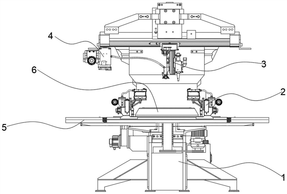
[0033] see figure 1 , in an embodiment of the present invention, a high-efficiency welding device based on high-power laser flying welding, which includes a frame 1, a positioning assembly 2, and a welding assembly 3, wherein the welding assembly 3 is slidably installed in the middle of the top of the frame 1 , and, the welding assembly 3 can slide left and right or forward and backward relative to the frame 1, so as to realize the linear welding of the workpiece; a worktable 5 is arranged directly below the welding assembly 3, and the middle part of the worktable 5 rotates A rotating disk 6 is provided, and the rotating disk 6 is driven to rotate by a rotating motor fixed below the frame 1; the positioning assembly 2 is symmetrically slid left and right on the rotating disk 6, and is driven to slide by the cylinder 15 fixed thereon ; The left side of the upper end of the frame 1 is also provided with a dust suction and purification device 4, and the dust suction and purificat...


PUM


Abstract

The invention discloses efficient welding equipment based on high-power laser flight welding. The efficient welding equipment based on high-power laser flight welding comprises a rack, positioning assemblies and a welding assembly, wherein the welding assembly is slidably mounted in the middle of the top end of the rack; the welding assembly can slide left and right or front and back relative to the rack so as to realize linear welding of a workpiece; a workbench is arranged under the welding assembly; a rotating disc is rotationally arranged in the middle of the workbench and is driven by a rotating motor fixed to the lower part of the rack to rotate; the positioning assemblies are slidably arranged on the rotating disc in a bilateral symmetry mode; a dust collection and purification device is further arranged on the left side of the upper end of the rack; the dust collection and purification device communicates with the welding assembly and is used for cleaning a welding area of the workpiece before welding and absorbing and purifying welding smoke dust; a clamping device is arranged in each positioning assembly and used for clamping and stabilizing the workpiece to be welded; and the inclination angle of each clamping device can be adjusted so as to adapt to welding of workpieces with different welding included angles.

Description

technical field [0001] The invention belongs to the technical field of laser welding, in particular to high-efficiency welding equipment based on high-power laser flying welding. Background technique [0002] Laser welding is a high-efficiency and precise welding method that uses a high-energy-density laser beam as a heat source. It is widely used due to its advantages such as fast welding speed and large aspect ratio; High-efficiency welding equipment for high-power laser flight welding often has the following problems: [0003] 1. When welding plate workpieces, it is fixed by manual fastening, which is cumbersome to operate; moreover, it cannot adjust the angle between the two plates, and cannot adapt to the welding work between plates with different angles. larger; [0004] 2. Before welding the plates, the welding area needs to be cleaned manually. Not only is the efficiency low, but also the cleaning is not thorough, so that debris remains in the welding area, resulti...

Claims


Application Information

Patent Timeline
IPC IPC(8): B23K26/21B23K26/70B23K26/142B23K37/04
CPCB23K26/21B23K26/702B23K26/142B23K37/0435
Inventor 马韬李欣明
Owner 苏州大鑫华激光科技有限公司
Why Eureka
Eureka Blog
Learn More