Eureka AIR delivers breakthrough ideas for toughest innovation challenges, trusted by R&D personnel around the world.

Differential parallel connecting rod linear parallel-clamping double-finger-section self-adaptive robot finger device

A robot finger, self-adaptive technology, applied in the directions of manipulators, chucks, joints, etc., can solve problems such as troublesome control of manipulators, collisions, inability to realize flat-clamp self-adaptive composite grasping mode, etc., and achieves low manufacturing and maintenance costs. Simple control and stable capture

Pending Publication Date: 2021-10-19
田源
View PDF0 Cites 0 Cited by
  • Summary
  • Abstract
  • Description
  • Claims
  • Application Information

AI Technical Summary

Problems solved by technology

[0003] The traditional flat clip adaptive finger is a flat clip adaptive finger with a circular arc trajectory at the end, which cannot realize the flat clip adaptive compound grasping mode with a straight line trajectory at the end. When grasping desktop objects, a mechanical arm is required to cooperate with the control Collaborative work can achieve more accurate object grasping, which brings trouble to the control of the robotic arm. When grasping objects of different sizes at the same time, the device needs to work at different heights, otherwise it is easy to cause the end fingers of the device to collide with the table. Danger

Method used


Image

  • Differential parallel connecting rod linear parallel-clamping double-finger-section self-adaptive robot finger device
  • Differential parallel connecting rod linear parallel-clamping double-finger-section self-adaptive robot finger device
  • Differential parallel connecting rod linear parallel-clamping double-finger-section self-adaptive robot finger device

Examples


Embodiment Construction

[0031] The specific structure and working principle of the present invention will be further described in detail below in conjunction with the accompanying drawings and embodiments.

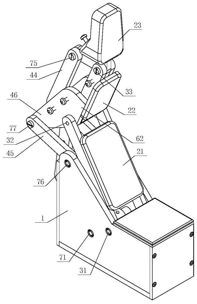
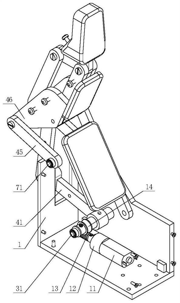
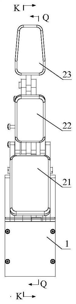
[0032] An embodiment of the differential parallel link linear flat clip dual-finger section self-adaptive robot finger device designed by the present invention, such as Figure 1 to Figure 8As shown, it includes a base 1, a first finger section 21, a second finger section 22, a third finger section 23, a proximal joint shaft 31, a middle joint shaft 32, a far joint shaft 33, a motor 11 and a transmission mechanism; the motor 11 is fixedly connected to the base 1, and the motor 11 is connected to the input end of the transmission mechanism; the joint-proximal shaft 31 is sleeved in the base 1, and the first finger section 21 is sleeved on the joint-proximal shaft 31, The middle joint shaft 32 is sleeved in the first finger segment 21, the second finger segment 22 is sleeved on the middle joint sha...


PUM


Abstract

The invention discloses a differential parallel connecting rod linear parallel-clamping double-finger-section self-adaptive robot finger device, and belongs to the technical field of robot hands. The device comprises a base, a motor, a transmission mechanism, three finger sections, a plurality of connecting rods, a plurality of shafts, two spring pieces, two limiting blocks and the like. According to the device, the motor, the transmission mechanism, the three finger sections, the plurality of connecting rods, the plurality of shafts, the two spring pieces, the two limiting blocks and the like are adopted to comprehensively achieve a three-joint linear parallel clamping and self-adaptive grabbing mode. In the initial stage, the device is in a linear parallel-clamping mode, that is, the third finger section translates, the track of the third finger section is approximate to a straight line, and the third finger section is suitable for clamping of an object on a plane; when the first finger section makes contact with the object and is blocked, the device enters the self-adaptive grabbing mode, the multiple finger sections make contact with the object, and the device has self-adaptability to objects of different shapes and sizes. Just one motor is used for driving three joints, control is easy, grabbing is stable, and the manufacturing and maintaining cost is low.

Description

technical field [0001] The invention belongs to the technical field of robot hands, and in particular relates to a structural design of a differential parallel link straight-line flat clip double-finger section self-adaptive robot finger device. Background technique [0002] The underactuated hand reduces the number of motors used, which enables the robot hand to reduce the requirements for the real-time sensing and control system of the hand while ensuring anthropomorphic movements. Existing underactuated fingers include flat pinch fingers, coupled fingers and adaptive fingers. The end of the flat grip finger maintains a constant posture relative to the base during the grasping process, which is suitable for grasping objects on the table; when the first segment of the coupling finger rotates, the third segment will rotate relative to the first segment at the same time , the grasping action is more anthropomorphic, and at the same time grasping is faster; the adaptive finge...

Claims


Application Information

Patent Timeline
Patent Type & Authority Applications(China)
IPC IPC(8): B25J15/02B25J17/02
CPCB25J15/0213B25J17/02
Inventor 田源张文增
Owner 田源
Why Eureka
Eureka Blog
Learn More