Double-wall cooling blade, turbine blade applying cooling blade and gas turbine

A technology for cooling blades and double walls, which is applied in the direction of supporting components of blades, mechanical equipment, engine components, etc., can solve the problems of complex manufacturing process, difficult core removal process of core manufacturing and engineering application, etc. Achieve the effects of improving life, improving cooling efficiency, and reducing manufacturing difficulty

Inactive Publication Date: 2021-10-19
FULL DIMENSION POWER TECH
View PDF5 Cites 3 Cited by
  • Summary
  • Abstract
  • Description
  • Claims
  • Application Information

AI Technical Summary

Problems solved by technology

[0004] However, in related technologies, the double-walled cooling structure is integrally formed by traditional casting methods, the manufacturing process is complicated, the manufacturing of the core and the core re

Method used


Image

  • Double-wall cooling blade, turbine blade applying cooling blade and gas turbine
  • Double-wall cooling blade, turbine blade applying cooling blade and gas turbine
  • Double-wall cooling blade, turbine blade applying cooling blade and gas turbine

Examples


Embodiment 1

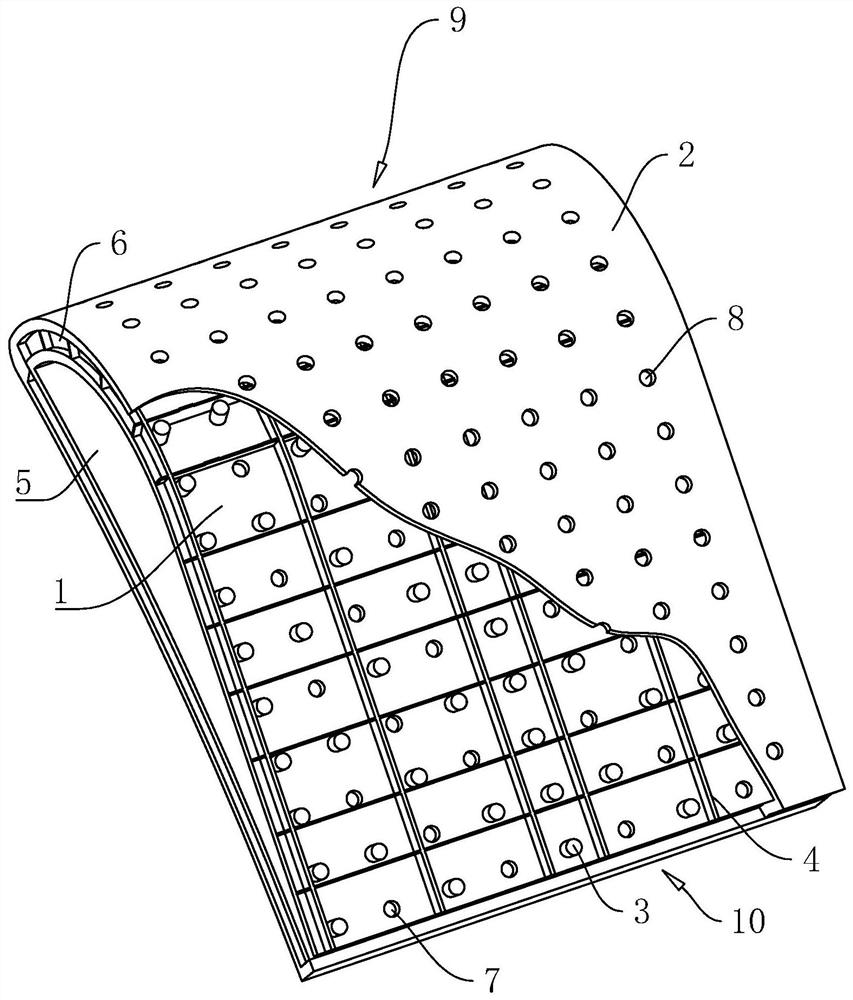
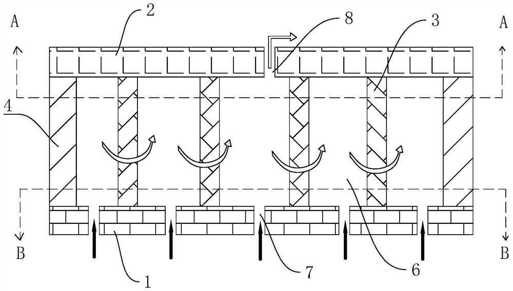
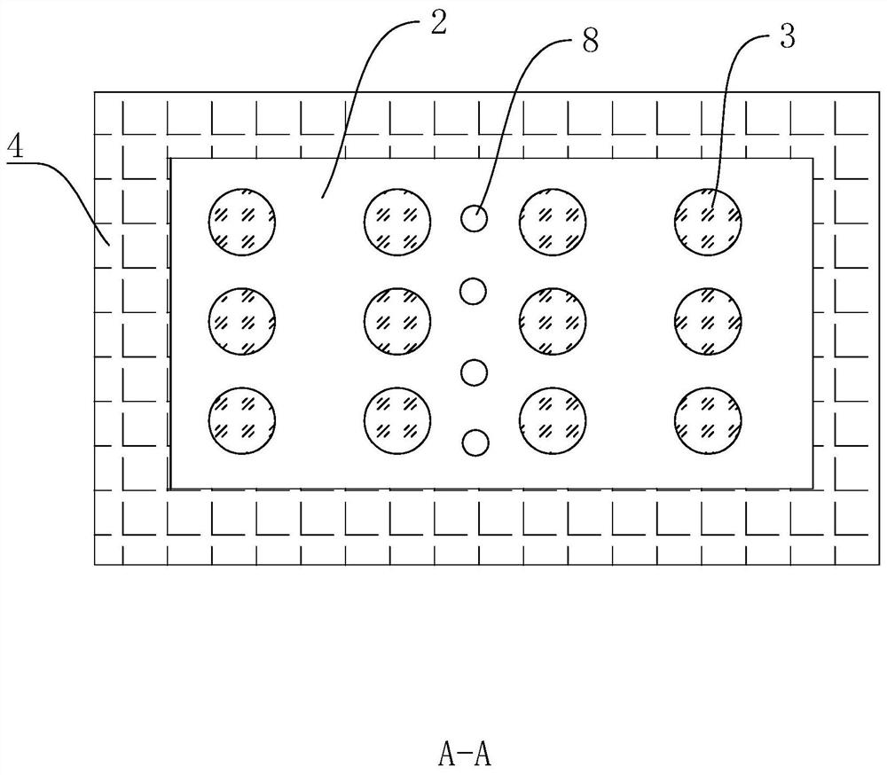
[0043] The embodiment of the present application discloses a double-walled cooling blade. refer to figure 1 , the double-walled cooling blade includes a blade inner wall 1 , a blade outer wall 2 , a heat exchange structure and a partition 4 . Wherein, the blade outer wall 2 is arranged around the periphery of the blade inner wall 1 , and the heat exchange structure and the partition plate 4 are both arranged between the blade inner wall 1 and the blade outer wall 2 . In this application, the outer wall 2 of the blade and the inner wall 1 of the blade are assembled and fixed after being separately processed, which can be processed and manufactured with low cost and high reliability under the existing technical conditions, and has important engineering practical value.

[0044] The inner wall 1 of the blade and the outer wall 2 of the blade can be in any shape, such as a rectangle, an irregular ring or a bow in cross-section, and the specific shape can be designed and selected ...

Embodiment 2

[0056] The difference between this embodiment and Embodiment 1 is that one side of the partition 4 is fixedly connected to the inner wall 1 of the blade by means of welding, or is cast integrally with the inner wall 1 of the blade, and the other side of the partition 4 is at least partly closely connected to the outer wall 2 of the blade. Abut.

[0057] And on the basis of this embodiment, in order to improve the assembly convenience of the blade inner wall 1 and the blade outer wall 2, the column rib 3 and the blade inner wall 1 are fixed by welding or integral casting.

Embodiment 3

[0059] The difference between this embodiment and Embodiment 1 is that one side of the partition 4 is fixedly connected to the outer wall 2 of the blade by welding, or is cast integrally with the outer wall 2 of the blade, and the other side of the partition 4 is at least partly closely connected to the inner wall 1 of the blade. Abut.

[0060] And on the basis of this embodiment, in order to improve the assembly convenience of the blade inner wall 1 and the blade outer wall 2, the column rib 3 and the blade outer wall 2 are fixed by welding or integral casting.


PUM


Abstract

The invention relates to a double-wall cooling blade, a turbine blade applying the cooling blade and a gas turbine. The double-wall cooling blade comprises a blade inner wall, a blade outer wall, a partition plate and heat exchange structures, wherein the blade inner wall is surrounded to form a high-pressure chamber; the blade outer wall is positioned on the outer side of the blade inner wall, and is detachably connected with the blade inner wall; the blade outer wall and the blade inner wall are surrounded to form an annular chamber; the partition plate is arranged in the annular chamber, and is used for dividing the annular chamber into a plurality of independent areas; the heat exchange structures are arranged in the independent areas; a plurality of impact holes for communicating the high-pressure chamber with the annular chamber are formed in the blade inner wall; and at least one row of cold air holes for communicating the annular chamber with the outside are formed in the blade outer wall. The double-wall cooling blade can solve the engineering application problem of a double-wall cooling structure.

Description

technical field [0001] The present application relates to the field of gas turbine cooling design, in particular to a double-walled cooling blade, a turbine blade using the cooling blade and a gas turbine. Background technique [0002] With the improvement of gas turbine design technology, the gas temperature at the inlet of gas turbine turbine continues to increase, and the heat load faced by turbine components is extremely high, which has already exceeded the limit that high-temperature materials can withstand. In order to ensure the safe and reliable operation of turbine blades, complex cooling design is required to keep the temperature and stress distribution of the blade body at a reasonable level. [0003] For example, in the cooling design of gas turbine blades with a temperature level of 1600 degrees Celsius (H-class gas turbine first-stage static and moving blades), the double-wall cooling structure has been considered, which is considered to be the one with the coo...

Claims


Application Information

Patent Timeline
IPC IPC(8): F01D5/18F01D5/14
CPCF01D5/18F01D5/186F01D5/147
Inventor 张正秋徐克鹏陈春峰王文三蒋旭旭陈江龙杨珑张磊
Owner FULL DIMENSION POWER TECH
Why Eureka
Try Eureka