Combined fuel supply device, combustion chamber and fuel supply method

An oil supply device and oil supply technology, which is applied in the directions of gas turbine devices, charging systems, turbine/propulsion fuel delivery systems, etc., to achieve uniform concentration distribution, full evaporation and blending, and improve the flight speed range.

Active Publication Date: 2021-10-19
NANJING UNIV OF AERONAUTICS & ASTRONAUTICS
View PDF6 Cites 2 Cited by
  • Summary
  • Abstract
  • Description
  • Claims
  • Application Information

AI Technical Summary

Problems solved by technology

[0003] Purpose of the invention: In order to solve the problem that the fuel oil can only be limited to the distribution of injection points in the prior art and limit the rapid spread of flames on the cross section, the present invention provides a combined fuel supply device that can take into account high temperature and large The problem of thermal protection under the condition of high flow and the problem of efficient combustion organization under the condition of low temperature and large flow

Method used


Image

  • Combined fuel supply device, combustion chamber and fuel supply method
  • Combined fuel supply device, combustion chamber and fuel supply method
  • Combined fuel supply device, combustion chamber and fuel supply method

Examples


Embodiment 1

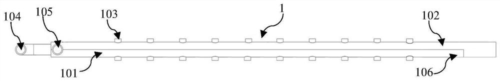
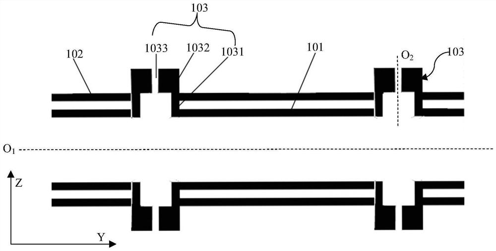
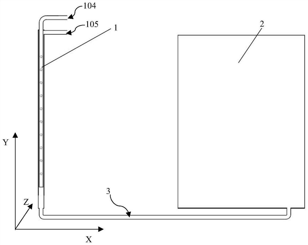
[0021] Embodiment 1: as figure 1 As shown, the oil supply mechanism 1 extends along the radial direction ( image 3 The direction in which the Y-axis extends), the fuel supply mechanism 1 includes a fuel injection rod 101 and is coaxial with the fuel injection rod 101 (O 1 ) are arranged on the oil supply pipe 102 outside the fuel injection rod 101, and the fuel injection rod 101 is provided with several fuel injection nozzles 103 for fuel injection. In this embodiment, the oil injection rod 101 supplies oil through the first oil inlet 104 , and the oil supply pipe 102 supplies oil through the second oil inlet 105 . Fuel can be selected to enter the fuel injection rod 101 from the first fuel inlet 104 or enter the fuel supply pipe 102 from the second fuel inlet 105 . In this embodiment, the difference between the outer diameter of the fuel injection rod 101 and the inner diameter of the fuel supply pipe 102 is 1-2mm, so that the fuel flowing through the outer fuel pipe can f...


PUM


Abstract

The invention discloses a combined fuel supply device, a combustion chamber and a fuel supply method. The combined fuel supply device comprises a fuel supply mechanism extending in the radial direction, a radial stabilizer arranged behind the fuel supply mechanism and a connecting section used for connecting the fuel supply mechanism and the radial stabilizer. The fuel supply mechanism comprises a fuel injection rod and a fuel supply pipe which is coaxially distributed with the fuel injection rod and arranged at the outer side of the fuel injection rod, a plurality of fuel injection nozzles which are used for fuel injection and distributed in the radial direction are formed in the fuel injection rod, openings of the fuel injection nozzles are located at the outer side of the fuel supply pipe, and the fuel injection direction of the fuel injection nozzles is perpendicular to the incoming flow direction. According to the combined fuel supply device, the thermal protection problem under the high-temperature large-incoming-flow condition and the efficient combustion organization problem under the low-temperature large-incoming-flow condition can be solved.

Description

technical field [0001] The invention relates to a combustion chamber of a sub-combustion ramjet engine, in particular to a combined fuel supply structure, combustion chamber and fuel supply method. Background technique [0002] When the sub-combustible ramjet engine works in the range of flight speed Ma2.0-Ma6.0 and altitude 5km-30km, the stabilizer faces the problem of thermal protection under the condition of high temperature and large influx and efficient combustion under the condition of low temperature and large influx organizational issues. In order to take into account the high-efficiency and reliable operation of the sub-combustion ramjet within the Ma2.0-Ma6.0 wide-area flight envelope, it is necessary to carry out high-altitude, high-temperature incoming flow conditions and low-altitude and large-flow conditions. Fuel supply scheme research. At present, the integrated stabilizer is widely used, that is, the rectifying support plate of the turbine exhaust frame an...

Claims


Application Information

Patent Timeline
Patent Type & Authority Applications(China)
IPC IPC(8): F02C7/22F02C3/14
CPCF02C7/22F02C3/14
Inventor 范育新姜凯琳陶华
Owner NANJING UNIV OF AERONAUTICS & ASTRONAUTICS
Why Eureka
Try Eureka