Supercharge Your Innovation With Domain-Expert AI Agents!

Jig for centering cutting of unilateral air gaps of small rectangular cores

A rectangular iron core, small technology, applied in the field of silicon steel coil iron core processing, to achieve the effect of simple structure, high production efficiency and convenient operation

Pending Publication Date: 2021-10-22
NICORE ELECTRICAL MFR CO LTD
View PDF7 Cites 0 Cited by
  • Summary
  • Abstract
  • Description
  • Claims
  • Application Information

AI Technical Summary

Problems solved by technology

[0004] The existing jig for cutting the air gap in the middle of the rectangular iron core has such shortcomings: the length of the inner ring of the rectangular iron core 1 in the cutting die assembly 3 is A±a, and the tolerance a is 0.2mm to 0.3mm. 2 To penetrate 8 to 12 rectangular iron cores 1, in order to ensure that the row of rectangular iron cores 1 can be inserted into the cutting die 2 smoothly, the width of the cutting die 2 should be 0.2mm smaller than the length of the inner ring of the rectangular iron core 1, that is, the cutting die 2 The width is A-a-0.2mm, that is to say, the maximum difference between the length of the inner ring of the rectangular iron core 1 and the width of the cutting die 2 is 2a+0.2mm, that is, the maximum gap between the inner ring of the rectangular iron core 1 and the side of the cutting die 2 is 0.6-0.8mm, a row of rectangular iron cores 1 of the cutting die assembly 3 placed on the first positioning groove 5-1-1 of the front and rear two baffle plates 5-1 before being clamped by the baffle plate 5-1 It is in a freely suspended state, and 8 to 12 rectangular iron cores 1 can make radial free displacement along the upper surface of the cutting die 2 in a space with a maximum gap of 0.6 to 0.8mm. In this way, when a row of rectangular iron cores After 1 is clamped by the baffle 5-1 and cut, there will be a small part of the center line of the air gap of the rectangular iron core 1 1 deviation from its nominal centerline 1 More than 0.2mm, become unqualified product

Method used


Image

  • Jig for centering cutting of unilateral air gaps of small rectangular cores
  • Jig for centering cutting of unilateral air gaps of small rectangular cores
  • Jig for centering cutting of unilateral air gaps of small rectangular cores

Examples


Embodiment Construction

[0020] The present invention is described in further detail by the following examples.

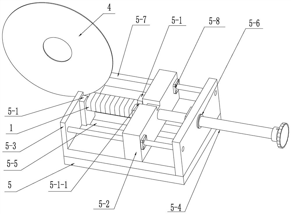
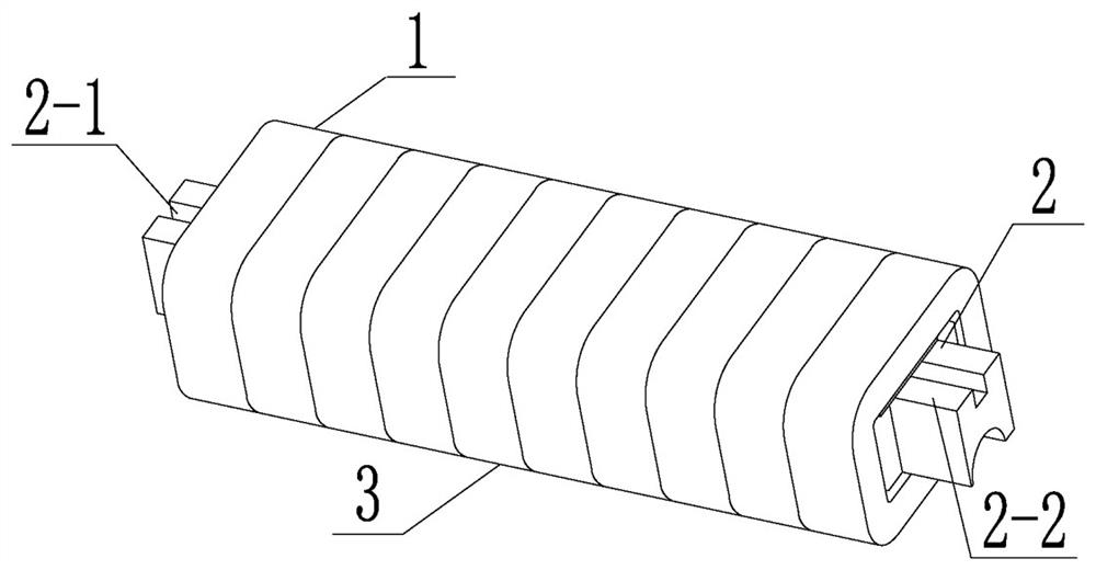
[0021] see Figure 1 to Figure 8 As shown, a small rectangular iron core unilaterally centered jig for cutting air gaps, including cutting clamps 5 and cutting dies 2, a row of n rectangular iron cores 1 inserted and supported on the cutting die 2, composed of The cutting die assembly 3 is also provided with an elastic positioning cutting die assembly 6, and the elastic positioning cutting die assembly 6 includes a base 6-1, side plates 6-2 arranged on the left and right sides of the base 6-1, the There are n equidistantly arranged elastic positioning members 6-3 arranged on the same level on the upper part of the two side plates 6-2. 1.0-1.5 mm, the bottom of the base 6-1 is matched and slidably connected with the second positioning groove 5-9 of the cutting clamp 5, and the cutting die assembly 3 is placed in the space formed by the two side plates 6-2. The front and rear positioning e...


PUM


Abstract

The invention discloses a jig for centering cutting of unilateral air gaps of small rectangular cores. The jig comprises a cutting clamp and an elastic positioning cutting die assembly, wherein the elastic positioning cutting die assembly comprises a base, two side plates and elastic positioning parts; a row of rectangular cores are sleeved with a cutting die to form the cutting die assembly; a row of elastic positioning parts are arranged at the same horizontal positions of the middle-upper parts of the two side plates; the bottom of the base is in matched sliding connection with a second positioning groove of the cutting clamp; the cutting die assembly is arranged in a space formed by the middle-upper parts of the two side plates; at the moment, two positioning ends of the cutting die are in matched positioning contact connection with a first positioning groove of the cutting clamp; and the centers of the left side surfaces and the right side surfaces of the rectangular cores are in contact connection with corresponding elastic positioning parts. According to the jig, the elastic positioning cutting die assembly is used for centering positioning of a row of rectangular cores subjected to air gap centering cutting, so that the reject ratio of products of small rectangular cores subjected to air gap centering cutting is zero.

Description

technical field [0001] The invention relates to the technical field of silicon steel coil iron core processing, in particular to a jig for unilaterally centering and cutting an air gap of a small rectangular iron core. Background technique [0002] A rectangular iron core wound with silicon steel sheets opens an air gap on the closed magnetic circuit. Its main function is to change the effective magnetic permeability of the magnetic core through the size of the air gap. Small iron cores with unilateral air gaps are widely used in electrical control systems. , communication systems, current transformers, Hall sensors, high-frequency transformers, reactors and other electrical components in power systems. Cutting the air gap on one side of the small rectangular iron core is an intermediate process step in the manufacturing process of this electrical component. In the next assembly process step, it needs to be put into the insulating sheath, the rectangular iron core and its ai...

Claims


Application Information

Patent Timeline
Patent Type & Authority Applications(China)
IPC IPC(8): B24B41/06B24B27/06
CPCB24B41/06B24B27/06
Inventor 张希望
Owner NICORE ELECTRICAL MFR CO LTD
Features
  • R&D
  • Intellectual Property
  • Life Sciences
  • Materials
  • Tech Scout
  • Unparalleled Data Quality
  • Higher Quality Content
  • 60% Fewer Hallucinations
Learn More