
Self-drilling nail clamp

A drilling tail and nail clip technology, which is applied in the manufacture of tools, nail dispensers, packaging, etc., can solve problems affecting work efficiency, endangering workers at heights, and potential safety hazards, achieving firmness, overcoming the shaking of drill tail nails, and installation convenient effect

Pending Publication Date: 2021-10-22
黄思忠
View PDF2 Cites 0 Cited by
  • Summary
  • Abstract
  • Description
  • Claims
  • Application Information

AI Technical Summary

Problems solved by technology

[0002] At present, the use of drill tail nails is usually installed on a tool of a U-shaped nail cap seat with a handle, and a magnet is inlaid in the U-shaped nail cap seat. This kind of tool has a certain adsorption force on the drill screw cap, but the control of this tool on the drill screw is not firm. Under the high-speed rotation of the electric drill, a certain thrust is required for the drill screw to drive into the material surface. If the center of gravity supports If the control is not good, it will be skewed, so that the fast-rotating drill screws will fall off and endanger the workers working at heights. At the same time, the electric drill will hit the material surface heavily and damage the material surface. big security risk
[0003] The invention patent application for the "safety protection device for installing external hexagonal self-drilling screws with pads" with the application number 201810446495.9 and the "drilling screw drill" with the application number 201911237405.6 solves the problem that the drilling screw is stuck when drilling. The claws are tightly held to eliminate potential safety hazards, but when installing each drill end screw with a hand electric drill, the operator must first pull back the casing on the drill bit, so that the movable jaws can be opened to insert the drill end screw into the nail. In the cap seat, it is necessary to repeat the operation every time a drilling nail is driven, so the structural design of the movable claw not only brings troubles to the operator during construction, but also affects the work efficiency; In this case, the pin holes on the movable jaws need to have a space for the jaws to open and close, so the movable jaws do not hold the drill tail screw firmly, that is, the drill tail screw shakes, and it is difficult for construction workers to locate. also can not hit the exact position

Method used


Image

  • Self-drilling nail clamp
  • Self-drilling nail clamp
  • Self-drilling nail clamp

Examples


Embodiment Construction

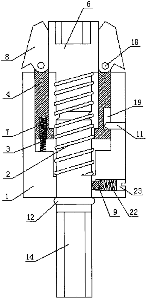
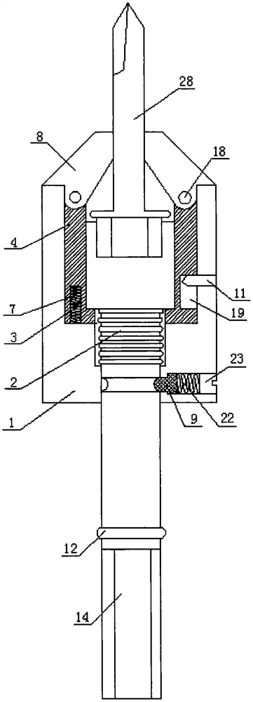
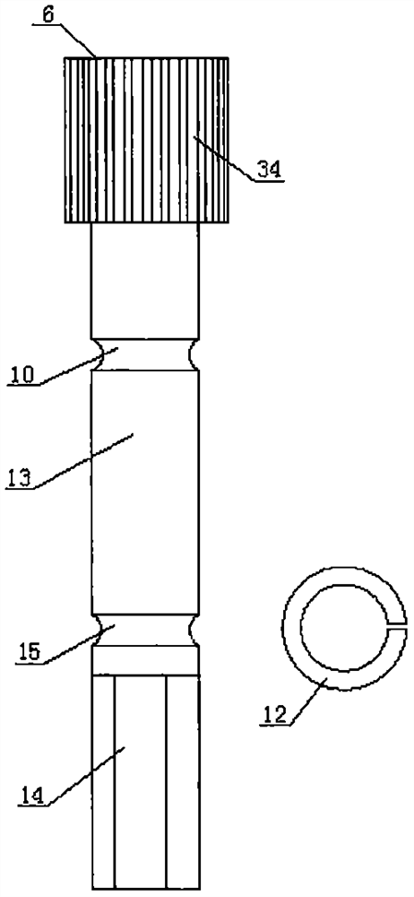
[0020] Such as figure 1 , figure 2 and image 3 As shown, the drill end nail clamp of this embodiment includes a nut base 6 , a magnet is arranged at the inner end of the nut base 6 , and a cylindrical nut rod 13 and a prismatic drill post 14 are formed at the rear end of the nail base 6 . The outer side of the nail cap seat 6 is provided with a nail cap seat tooth bar 34, the nail cap bar 13 is provided with a ring shaft groove 10, and between the ring shaft groove 10 and the drill clamp post 14 is provided with a terminal ring groove 15, and the terminal ring groove 15 is installed There is an end ring 12, the diameter of the nail cap seat 6 is greater than the nail cap rod 13, and the outer side of the nail cap seat 6 is sequentially sleeved with an inner tube body 4 and an outer tube body 1 from inside to outside. The weak spring 2 is sleeved on the nail cap rod 13, and the outer diameter of the end ring 12 is greater than the inner diameter of the inner wall of the out...


PUM


Abstract

The invention discloses a self-drilling nail clamp, and relates to the field of self-drilling nail tools. The self-drilling nail clamp solves the problems that an existing self-drilling nail cap cannot firmly hold a self-drilling nail, time is wasted for constructors, and accurate positioning is difficult. According to the self-drilling nail clamp, an inner pipe body and an outer pipe body are sequentially sleeved on the outer side of a nail cap seat of the self-drilling nail clamp from inside to outside, a spring hole for placing a clutch spring is formed in a port of the inner end of the inner pipe body, an outer pipe body rack meshed with an inner pipe body outer rack is arranged on the inner wall of the outer pipe body, the outer pipe body is connected to the inner pipe body in a sleeved mode, a pressure adjusting hole corresponding to a nail cap seat ring shaft groove is formed in the lower portion of the outer pipe body, and a weak spring is sleeved on a nail cap rod. The self-drilling nail clamp is safe, reliable, time-saving and labor-saving, and accurate positioning can be realized.

Description

technical field [0001] The invention relates to the field of drill tail nail tools, in particular to a drill tail nail clamp. Background technique [0002] At present, the use of drill tail nails is usually installed on a tool of a U-shaped nail cap seat with a handle, and a magnet is inlaid in the U-shaped nail cap seat. This kind of tool has a certain adsorption force on the drill screw cap, but the control of this tool on the drill screw is not firm. Under the high-speed rotation of the electric drill, a certain thrust is required for the drill screw to drive into the material surface. If the center of gravity supports If the control is not good, it will be skewed, so that the fast-rotating drill screws will fall off and endanger the workers working at heights. At the same time, the electric drill will hit the material surface heavily and damage the material surface. A big security risk. [0003] The invention patent application for the "safety protection device for ins...

Claims


Application Information

Patent Timeline
Patent Type & Authority Applications(China)
IPC IPC(8): B25C3/00
CPCB25C3/006
Inventor 黄思忠
Owner 黄思忠
Learn More