A prefabricated slab for prefabricated buildings, a connection method between the prefabricated slab and the beam, and a construction method

A technology of construction method and connection method, which is applied in the directions of buildings, building components, building structures, etc., can solve the problems of difficult occlusion of adjacent prefabricated panels, difficulty in ensuring construction quality, and difficulty in pin positioning, so as to achieve overall firmness, reduce Concrete dosage and excellent quality

Active Publication Date: 2019-10-29
厦门华旸建筑工程设计有限公司
View PDF11 Cites 0 Cited by
  • Summary
  • Abstract
  • Description
  • Claims
  • Application Information

AI Technical Summary

Problems solved by technology

[0005] The present invention aims to provide a prefabricated slab for prefabricated buildings, a connection method between the prefabricated slab and beams and a construction method, so as to solve the difficulties in positioning pins in the existing prefabricated slabs, the difficulty of interlocking adjacent prefabricated slabs and the large amount of on-site welding and other shortcomings, as well as problems such as poor construction accuracy, complicated process, long construction period and difficulty in guaranteeing construction quality.

Method used


Image

  • A prefabricated slab for prefabricated buildings, a connection method between the prefabricated slab and the beam, and a construction method
  • A prefabricated slab for prefabricated buildings, a connection method between the prefabricated slab and the beam, and a construction method
  • A prefabricated slab for prefabricated buildings, a connection method between the prefabricated slab and the beam, and a construction method

Examples


Embodiment 1

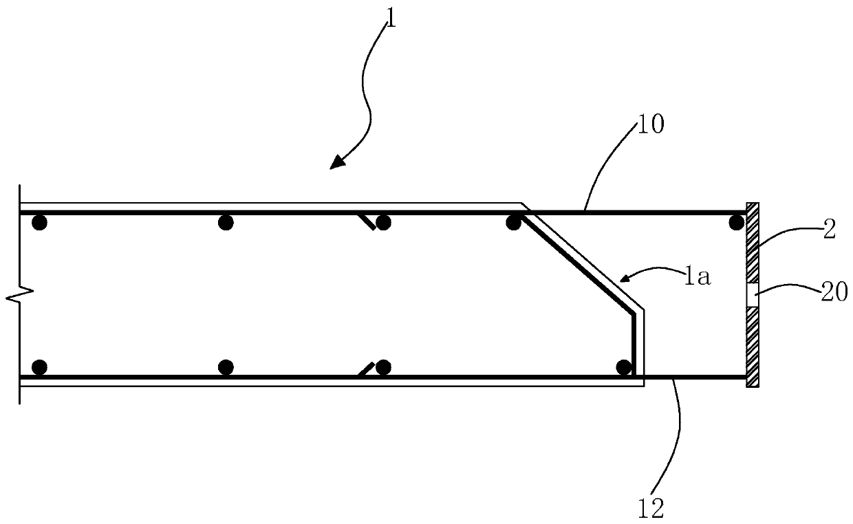
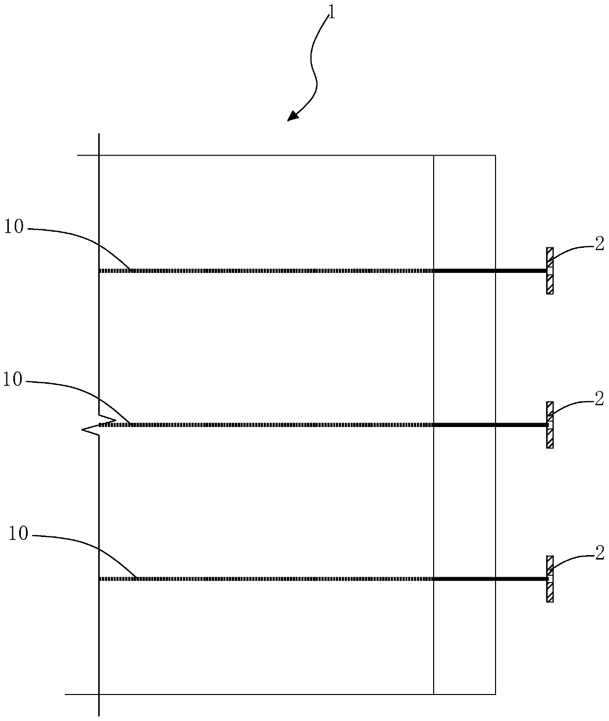
[0037] The invention provides a prefabricated panel for prefabricated buildings, such as figure 1 with figure 2 As shown, the prefabricated slab body 1 is included, and the prefabricated slab body 1 has plate gluten 10 and slab bottom rib 12, and the slab gluten 10, slab bottom rib 12 and other longitudinally arranged steel bars are welded to form a steel skeleton, defining the prefabricated slab body 1 The end face connected to the beam is the joint surface 1a, and the surface of the joint surface 1a is roughened to make it a rough surface with a concave-convex difference of not less than 6mm, so as to increase the bonding force of the concrete poured in the edge seam of the slab. A plurality of panel gluten bars 10 and a plurality of panel bottom ribs 12 in the prefabricated panel body 1 all extend to the outside of the joint surface 1a, and there are a plurality of connecting plates 2 arranged at intervals along the length direction of the joint surface outside the joint s...

Embodiment 2

[0045] The present invention also provides a connection method and construction method between prefabricated slabs and beams, refer to Figure 1-Figure 8 , including the following steps,

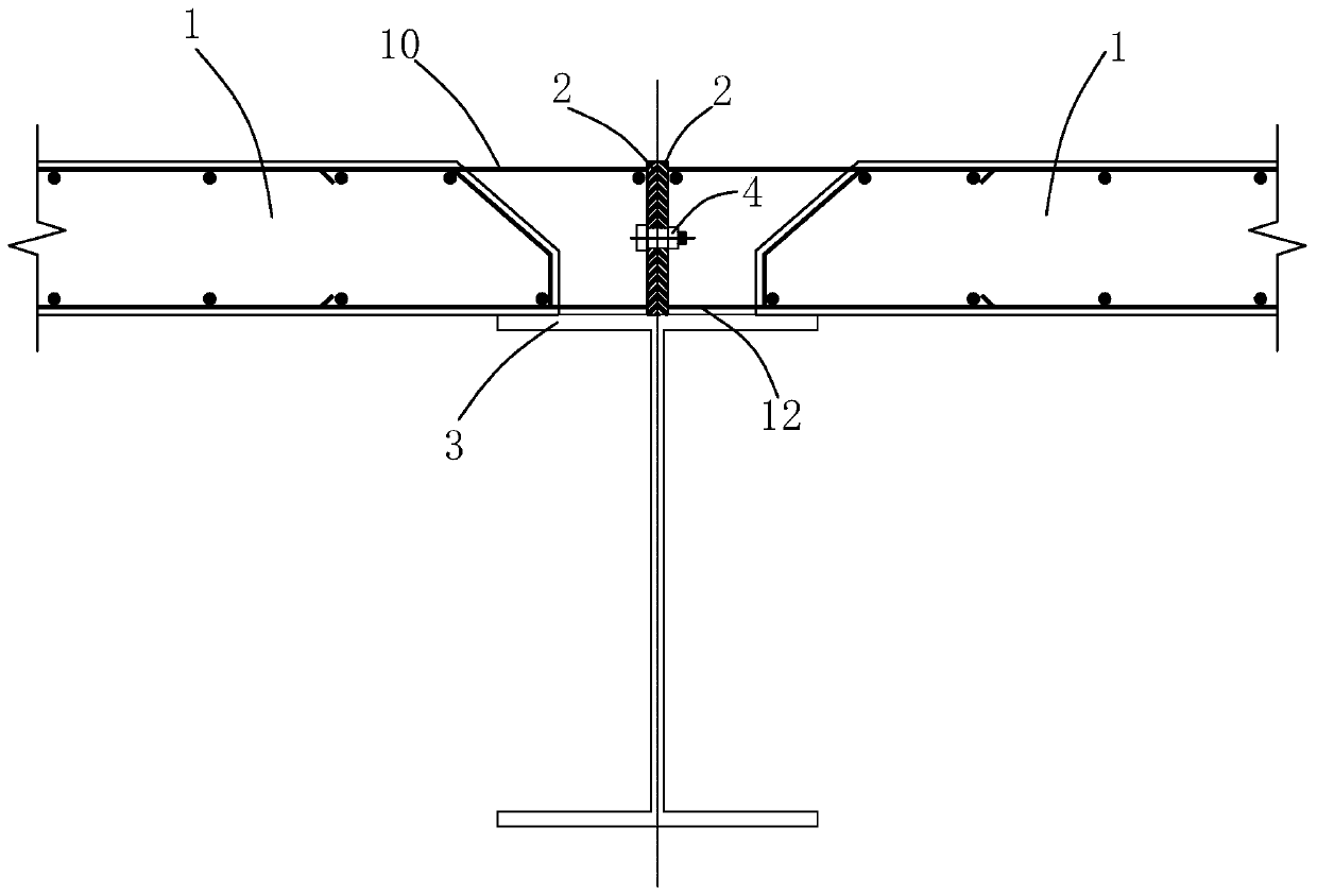
[0046] S1. Beams and prefabricated slabs are provided, wherein the prefabricated slab is any one of the prefabricated slabs described in Embodiment 1, and the bearing surface of the beam 3 has a shear connector 6;

[0047] S2. Hoist the prefabricated slab. After the prefabricated slab is hoisted in place, use bolts on site to lock the connecting plates on the prefabricated slabs on both sides of the beam (the length of the end of the prefabricated slab resting on the beam should not be less than 30mm, and the bolts should be M16, and Meet the structural requirements of "Code for Design of Concrete" GB 50010, "Code for Design of Steel Structure" GB 50017 and other relevant specifications);

[0048] S3. Pouring concrete strips, pouring self-compacting concrete strips at the boundary joints of...


PUM


Abstract

The invention relates to a prefabricated slab for prefabricated buildings, a connection method between the prefabricated slab and beams and a construction method, wherein the prefabricated slab includes a prefabricated slab body, and the prefabricated slab body has slab gluten and slab bottom ribs inside, defining the prefabricated slab The end face connecting the body and the beam is the joint surface. The multiple slab gluten and the multiple slab bottom ribs in the prefabricated slab body extend to the outside of the joint surface. The plate is fixedly connected with the plate ribs and the plate bottom ribs, and bolt lock holes are reserved on the connecting plate to solve the shortcomings of existing prefabricated panels such as difficult positioning of pins, difficulty in occlusion of adjacent prefabricated panels, and large amount of on-site welding; The invention also provides the connection mode and construction method of the prefabricated board and the beam.

Description

technical field [0001] The invention relates to the field of prefabricated buildings, in particular to a prefabricated panel for the prefabricated building, a connection method between the prefabricated panel and a beam, and a construction method. Background technique [0002] Prefabricated steel structure building is a main form of prefabricated building, which has the advantages of "light, fast, good, and economical". The use of prefabricated panels will greatly reduce the on-site workload and construction waste of prefabricated steel structure buildings, which will help speed up Construction speed, shorter construction period, and more environmentally friendly. [0003] The current prefabricated steel structure floor system still mostly adopts traditional construction methods, which cannot meet the needs of the rapid development of prefabricated buildings. The main forms of steel structure floors include profiled steel plate composite floor, reinforced truss floor deck c...

Claims


Application Information

Patent Timeline
Patent Type & Authority Patents(China)
IPC IPC(8): E04B5/02E04B1/38
CPCE04B5/02E04B5/023E04B1/388
Inventor 钱钧珑马晓勤汤德英
Owner 厦门华旸建筑工程设计有限公司
Why Eureka
Try Eureka