Clamp and assembling robot
A gripper and gripper technology, applied in the field of grippers and assembling robots, can solve the problems of difficulty in finding fasteners, low compatibility, and increased operating costs, so as to improve convenience and safety, and improve compatibility. sex, improve compatibility
- Summary
- Abstract
- Description
- Claims
- Application Information
AI Technical Summary
Problems solved by technology
Method used
Image

Examples
Embodiment 1
[0043] Fasteners are widely used. On mechanical equipment and electrical equipment, the most common fasteners are bolts and nuts. However, from heavy machinery to light industrial equipment, the size and type of fasteners are often varied, and even in the same equipment, due to the differences in various sub-components, there will be fasteners of various types and sizes. During equipment installation and maintenance, the operator must be equipped with grippers of various types and sizes to respectively grip these fasteners in order to complete the work.
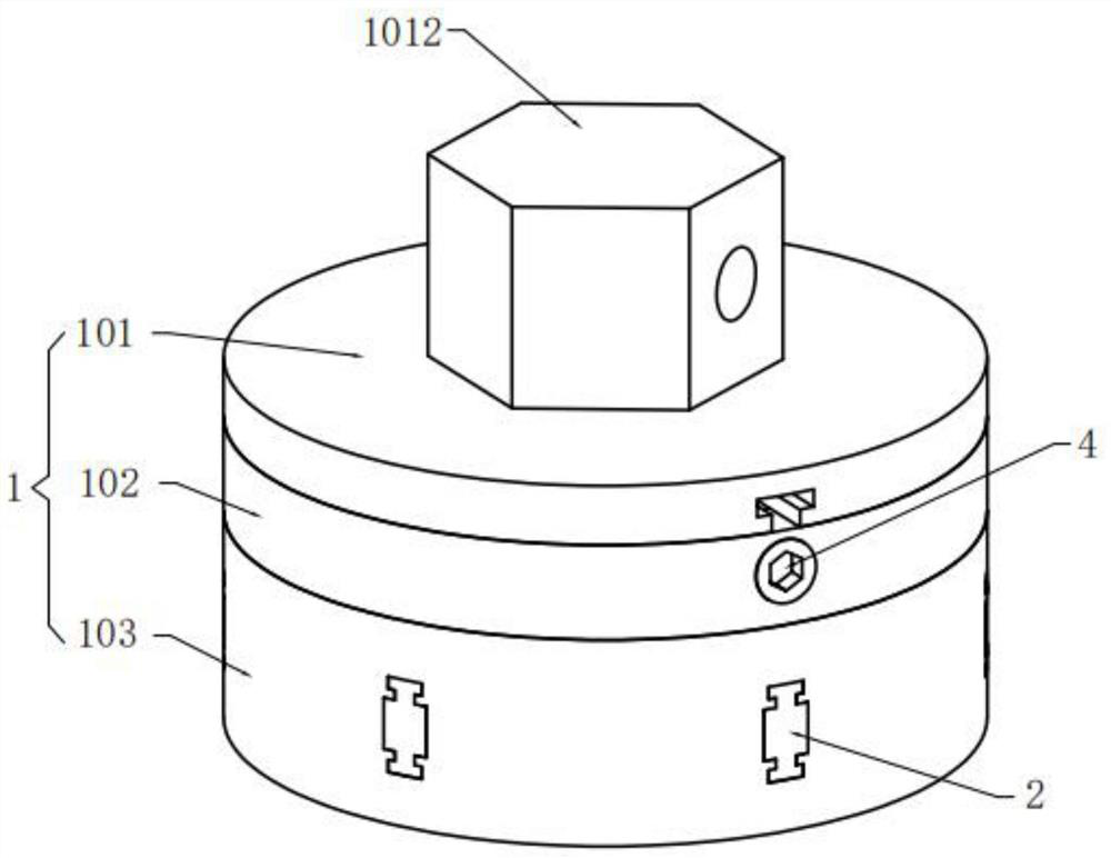
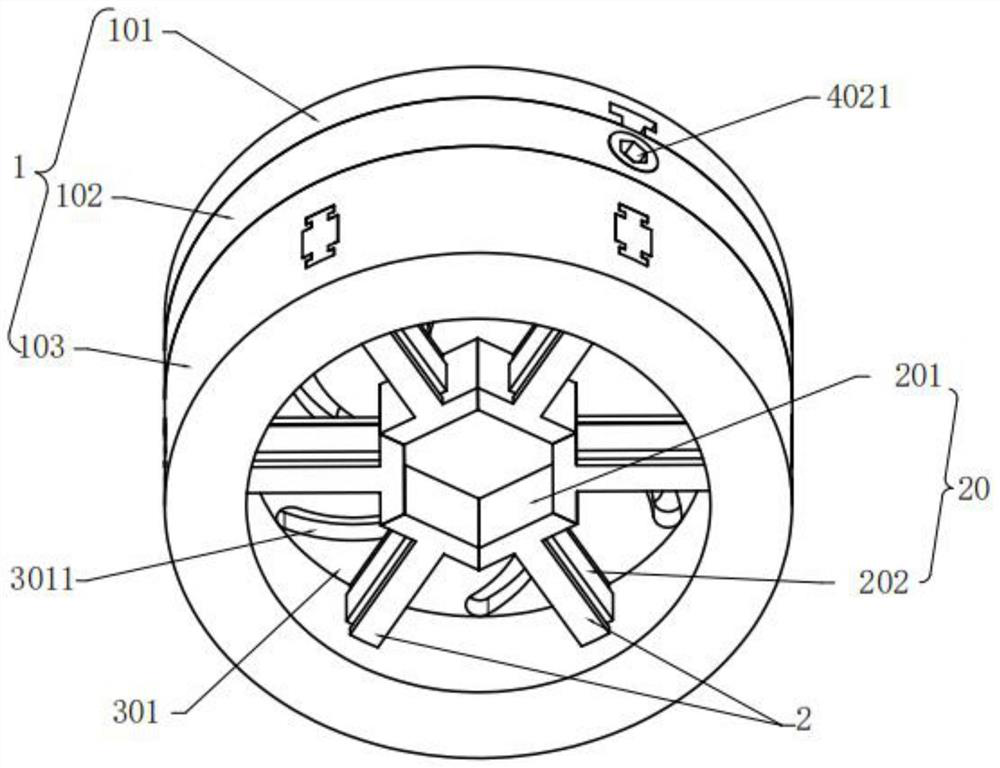
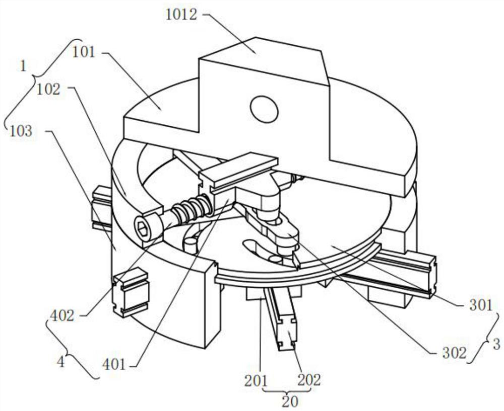
[0044] Such as Figure 1-Figure 2 As shown, this embodiment provides a clamper, which can achieve the purpose of clamping objects to be clamped of different types and sizes by adjusting the movement of each clamping member 20. It has high compatibility and simple structure. Easy to operate. Specifically, the clamper includes: a mounting base 1 , a clamping component 2 , a linkage component 3 and a driving component 4 .
[...
Embodiment 2
[0066]This embodiment provides a clamper, which is basically the same as the clamper in Embodiment 1, the main difference is that: in this embodiment, at least two linkage guide rods are provided on the linkage plate 301, each Each clamping piece 20 is provided with a linkage guide groove, and the linkage guide rods slide and fit in the linkage guide groove one by one. Exemplarily, on the linkage plate 301, there are six vertically downward linkage guide rods symmetrically distributed about the center, and the side close to the clamping part 201 above the first guide rail 2021 above each limiter 202 is connected to There is an arc-shaped linkage guide groove, and each linkage guide rod is inserted into a one-to-one corresponding linkage guide groove; when the linkage disk 301 is rotated, the linkage guide rod rotates and slides in its one-to-one corresponding linkage guide groove , so as to drive the limiting part 202 to move linearly in the limiting groove 1031, so that the c...
Embodiment 3
[0068] This embodiment provides a clamper, which is basically the same as the clamper in Embodiment 1, the main difference is that: in this embodiment, the drive assembly includes a timing belt, and timing gears are connected to both ends of the timing belt Rotating the synchronous gear at one end can realize the synchronous belt walking, the synchronous belt and the interlocking disc 301 are connected by the driving gear, the synchronous belt traveling can drive the driving gear to rotate, and the driving gear rotates to drive the interlocking disc 301 to rotate. Optionally, the number of stages of the driving gear is not limited. The synchronous belt is used to realize the rotation control of the linkage disc 301, eliminating the need for the setting of the swing rod 302, the structure is simple, the cost is low, the transmission efficiency is improved, and the rotation of the linkage disc 301 can still be precisely controlled to control the clamping parts 20 , so as to real...
PUM
 Abstract
Description
Claims
Application Information
 - R&D
- Intellectual Property
- Life Sciences
- Materials
- Tech Scout
- Unparalleled Data Quality
- Higher Quality Content
- 60% Fewer Hallucinations
Browse by: Latest US Patents, China's latest patents, Technical Efficacy Thesaurus, Application Domain, Technology Topic, Popular Technical Reports.
© 2025 PatSnap. All rights reserved.Legal|Privacy policy|Modern Slavery Act Transparency Statement|Sitemap|About US| Contact US: help@patsnap.com