Modeling method for modular splicing type complex terrain

A technology of complex terrain and modeling method, applied in the direction of hydraulic model, etc., can solve the problems such as non-reusable markers, increase of model making errors, destruction of original terrain, etc. Terrain effect

Inactive Publication Date: 2021-10-22
TIANJIN PORT ENG INST LTD OF CCCC FIRST HARBOR ENG +2
View PDF6 Cites 0 Cited by
  • Summary
  • Abstract
  • Description
  • Claims
  • Application Information

AI Technical Summary

Problems solved by technology

However, when the terrain is complex, especially when the mountains are steep, there are many islands, and buildings intersect in multiple directions, this method has great disadvantages, mainly reflected in: 1. When the terrain is complex, in order to accurately simulate the boundary and contour of the terrain The direction of the line needs to fix a lot of markers, and many markers make it difficult to make a model, especially in the process of sand filling, which will cause the markers to move or tilt, resulting in an increase in model making errors; 2. For the model The production workers have extremely high requirements. On the one hand, during the sand filling process, it is necessary to ensure that the markers remain upright and cannot move; on the other hand, during the plastering process, they must ensure that the markers can be connected smoothly
3. When simulating the construction of marine structures, it is necessary to destroy the original terrain. At this time, there is a risk of losing the original markers
4. Markers cannot be reused, resulting in a large waste
This process needs to pay great attention to the stability of the wooden pile. When the forklift is unloading sand, it is easy to skew the wooden pile or even shift its position. In complex terrain, such as the above-mentioned mountains, it is often impossible to carry out mechanical sand unloading and requires manual precision. flat, very labor intensive

Method used


Image

  • Modeling method for modular splicing type complex terrain
  • Modeling method for modular splicing type complex terrain
  • Modeling method for modular splicing type complex terrain

Examples


Embodiment Construction

[0038] In order to make the object, technical solution and advantages of the present invention more clear, the present invention will be further described in detail below in conjunction with the examples. It should be understood that the specific embodiments described here are only used to explain the present invention, not to limit the present invention.

[0039] A modeling method of modular splicing complex terrain, comprising the following steps:

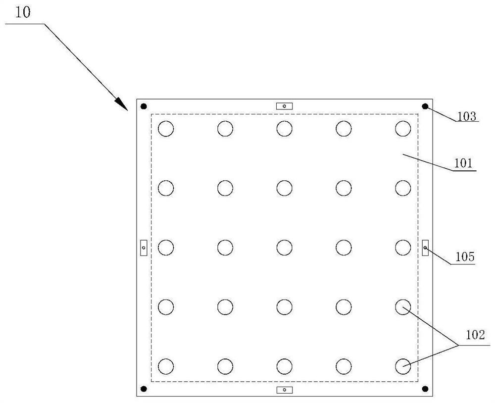
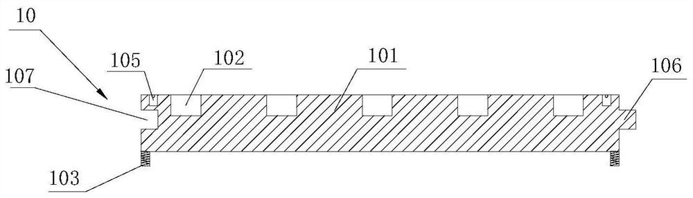
[0040] S1. First, make a modular modeling unit for backup, please refer to figure 2 and Figure 6 , the modular modeling unit 10 includes a square base base 101, the upper and lower surfaces of the base base are horizontal reference planes, and n×n card slots 102 are equidistantly arranged on the upper surface of the base, and the base base Adjustable height knobs 103 are installed at the four corners of the lower surface; it also includes a telescopic ruler 104 for accurately simulating the height of the terrain; the telescopic...


PUM


Abstract

The invention discloses a modeling method for a modular splicing type complex terrain. The modeling method comprises the following steps that S1, firstly, modular modeling single bodies are manufactured for later use; S2, according to the specifications of the modular modeling single bodies, high-precision grid interpolation is carried out on the complex terrain; S3, elevation coordinates of the modular modeling single bodies are locked, and numbering is carried out on each modular single body; S4, sand filling is conducted; S5, plastering is conducted; S6, after the construction of the original terrain is completed, simulating is carried out on the building, and lofting and construction of the building are carried out according to the mark points which are embedded in advance; and S7, after the building is completed, model manufacturing is basically finished. The modularized modeling single body is used so that accurate simulating can be carried out on the complex terrain, the height of the terrain can be accurately simulated through telescopic scales, and therefore the model manufacturing precision can be greatly improved, and the model manufacturing speed can be greatly improved; and a modular splicing mode is adopted, and after numbering is carried out on each module, the modules can be assembled at any place and are not limited by places.

Description

technical field [0001] The invention belongs to the technical field of terrain modeling, and in particular relates to a modeling method of modular splicing complex terrain. Background technique [0002] In the hydraulic construction process of new nuclear power plants, ports, ship locks, etc., when it is necessary to solve engineering and scientific research related issues such as structural design and layout, it is necessary to conduct mathematical and physical model test research. The basis of physical model test research is to prepare and simulate the model to truly reflect the topography of the project area, the appearance of buildings and related parameters. The physical model making of the hydraulic test is actually the same as the sand table in the sales office. After a certain proportion of zooming, the real object is presented in a smaller range. There are many types of hydraulic model test models, including docks and nuclear power plants. At the same time Includin...

Claims


Application Information

Patent Timeline
Patent Type & Authority Applications(China)
IPC IPC(8): E02B1/02
CPCE02B1/02
Inventor 孙运佳吕迎雪丁广佳何平佟德胜李泽孔从颖
Owner TIANJIN PORT ENG INST LTD OF CCCC FIRST HARBOR ENG
Why Eureka
Try Eureka