Exhaust pipe and exhaust cavity assembly for rotor compressor

A technology of rotor compressor and exhaust pipe, which is applied to components of pumping devices for elastic fluid, pump components of rotary piston type/swing piston type, mechanical equipment, etc. Problems such as air cavity and large noise can reduce exhaust pulsation and noise, extend the running path, and reduce the flow rate.

Pending Publication Date: 2021-10-22
黄石东贝压缩机有限公司
View PDF2 Cites 0 Cited by
  • Summary
  • Abstract
  • Description
  • Claims
  • Application Information

AI Technical Summary

Problems solved by technology

[0003] With the improvement of living standards, people have higher and higher requirements for the use of compressors. Loud noise and compressor oil injection are the most difficult problems in the existing compressor technology, and the exhaust noise is the main noise source of the compressor. One of them, and the oil injection problem will cause the refrigeration system to not cool, the pipes will be blocked or even completely scrapped
[0004] China (CN111706510A) discloses a new rotor compressor with flexible connection and direct suction, which includes a casing, and a pump body is installed inside the casing through a plurality of elastic supports, and the pump body includes a cylinder assembly. A crankshaft is sleeved on the cylinder assembly, and a motor is sleeved above the crankshaft; the pump body also includes a swing or sliding rotor arranged in the cylinder assembly, and the rotor is sleeved with the crankshaft; the rotor The slide plate is connected with the cylinder assembly, and the rotor and the slide plate divide the inner cavity of the cylinder assembly into a low-pressure chamber and a high-pressure chamber; the low-pressure chamber is connected with a suction muffler chamber through an air intake passage, so The suction muffler chamber is connected to the shell suction pipe through a suction flexible connecting pipe; the high pressure chamber is connected to the exhaust muffler chamber through an exhaust passage, and the exhaust muffler chamber communicates with the inner cavity of the casing; Although there is a muffler, its specific structural plan has not been announced, nor has an exhaust cavity been set at the exhaust pipe in the casing to reduce noise and prevent fuel injection

Method used


Image

  • Exhaust pipe and exhaust cavity assembly for rotor compressor
  • Exhaust pipe and exhaust cavity assembly for rotor compressor
  • Exhaust pipe and exhaust cavity assembly for rotor compressor

Examples


Embodiment 1

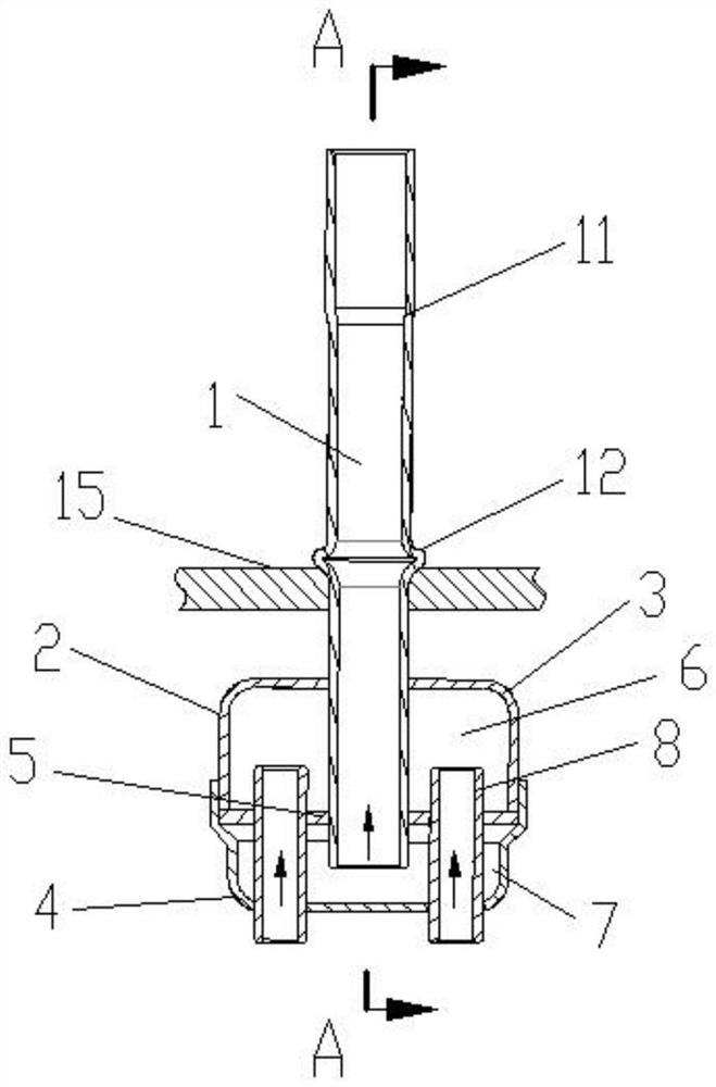
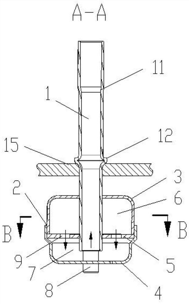
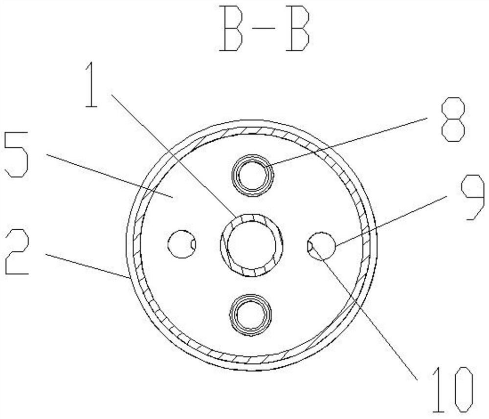
[0041] Such as Figure 1-4 As shown, an exhaust pipe and exhaust chamber assembly for a rotary compressor, the exhaust chamber 2 includes a first end cover 3 and a second end cover 4 fixedly connected, the first end cover 3 A partition 5 is fixed between the second end cover 4 and the space formed by the partition 5 and the first end cover 3 constitutes a first cavity 6, and the partition 5 and the second end cover The space formed by the cover 4 constitutes a second cavity 7, and two air intake pipes 8 are connected between the partition plate 5 and the second end cover 4, and the air intake pipes 8 communicate with the first cavity 6 Outside the exhaust chamber 2, two vent holes 9 are opened on the partition 5, and the air inlet end of the exhaust pipe 1 runs through the first end cover 3 and the partition 5, so The intake end of the exhaust pipe 1 is located in the second cavity 7 , and the exhaust pipe 1 passes through and is connected with the casing 15 of the compressor...

Embodiment 2

[0059] Such as Figure 5 As shown, this embodiment is an exhaust pipe and exhaust cavity assembly for a rotary compressor, which is further optimized on the basis of Embodiment 1:

[0060] Further, the partition plate 5 is provided with a boss 13 located on the periphery of the intake end of the exhaust pipe 1 , and two layers of filter screens 14 are fixed inside the boss 13 . The fixing method can be welded, glued or clamped.

[0061] By arranging the boss 13 and the strainer 14, the oil liquid is better prevented from being sprayed out of the exhaust pipe 1, and the blocked oil liquid will flow back into the compressor from the oil leakage hole 10.


PUM


Abstract

The invention discloses an exhaust pipe and exhaust cavity assembly for a rotor compressor. An exhaust cavity comprises a first end cover and a second end cover which are fixedly connected, wherein a partition plate is fixed between the first end cover and the second end cover; a first cavity is formed by a space formed by the partition plate and the first end cover; a second cavity is formed by a space formed by the partition plate and the second end cover; a plurality of air inlet pipes are connected between the partition plate and the second end cover in a penetrating mode and communicated with the first cavity and the outside of the exhaust cavity; a plurality of vent holes are further formed in the partition plate; the air inlet end of the exhaust pipe penetrates through the first end cover and the partition plate; the air inlet end of the exhaust pipe is located in the second cavity; and the exhaust pipe is connected with a shell of the compressor in a penetrating mode. According to the exhaust pipe and exhaust cavity assembly, the operation exhaust noise of the compressor can be reduced, and the oil injection of the compressor can be reduced.

Description

technical field [0001] The invention belongs to the technical field of refrigeration equipment, and in particular relates to an exhaust pipe and an exhaust chamber assembly for a rotor compressor. Background technique [0002] A compressor is a driven fluid machine that elevates low-pressure gas to high-pressure gas, and is the heart of the refrigeration system. It inhales low-temperature and low-pressure refrigerant gas from the suction pipe, drives the piston to compress it through the operation of the motor, and discharges high-temperature and high-pressure refrigerant gas to the exhaust pipe to provide power for the refrigeration cycle. The rotary compressor is one of the compressors. The rotary compressor is divided into two types, one is the fixed vane type, and the other is the sliding vane type. The rotor of the stator type rotary compressor is installed on the eccentric shaft, and the volume changes when it rotates, and the cylinder is separated by the stator. A v...

Claims


Application Information

Patent Timeline
Patent Type & Authority Applications(China)
IPC IPC(8): F04C29/12F04C29/06F04C29/02F04C29/00
CPCF04C29/12F04C29/065F04C29/026F04C29/0092
Inventor 杨百昌邹红戴竟雄甘念秦道乾
Owner 黄石东贝压缩机有限公司
Why Eureka
Try Eureka