Optimization method suitable for rotating shaft laser radar

A technology of laser radar and optimization method, applied in the field of laser scanning, can solve problems such as imaging distortion, and achieve the effect of optimizing distortion and improving quality

Pending Publication Date: 2021-10-22
BEIJING UNIV OF TECH
View PDF0 Cites 0 Cited by
  • Summary
  • Abstract
  • Description
  • Claims
  • Application Information

AI Technical Summary

Problems solved by technology

[0009] The invention is used to solve the problem of imaging distortion caused by the torque disturbance caused by the gravity of the rotation axis laser radar

Method used


Image

  • Optimization method suitable for rotating shaft laser radar
  • Optimization method suitable for rotating shaft laser radar
  • Optimization method suitable for rotating shaft laser radar

Examples


Embodiment Construction

[0027] Specific embodiments of the present invention will be further described in detail below in conjunction with the accompanying drawings.

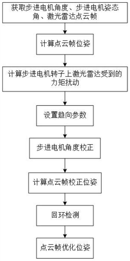
[0028] In order to optimize the scanning point cloud distortion caused by the torque disturbance of the rotary axis laser radar when the external rotation axis is rotated, the present invention provides an optimization method suitable for the rotary axis laser radar, and the specific implementation is as follows:

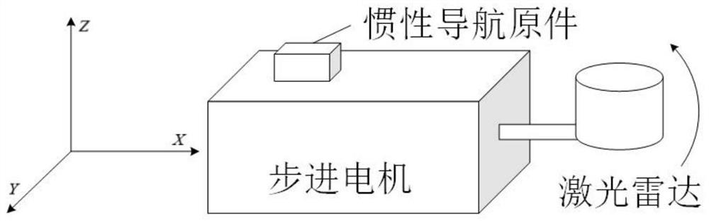
[0029] In this embodiment, a handheld rotary laser radar is used, such as figure 2 As shown, 5 times of scanning tests were carried out, and the scanning objects were three balls hanging in the long through corridor, the diameters of which were 18cm, 15cm, and 23cm respectively.

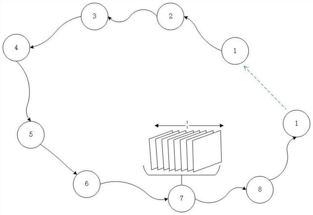
[0030] The scanning method adopts the three-time reciprocating motion of the rotation axis lidar around the ball, up, down, back, left, right, and left, to scan the shape of the whole ball.

[0031] The laser radar in the rotary axis laser radar ...


PUM


Abstract

The invention provides an optimization method suitable for a rotating shaft laser radar. According to the method, trend parameters are dynamically set through the pose of a stepping motor, the angle of the stepping motor, the gravity of the laser radar and the fixed position of the laser radar. And according to the trend parameters, the angle data of the stepping motor corresponding to the laser radar point cloud frame is scaled so as to correct the angle data of the stepping motor, then the corrected pose of the point cloud frame is calculated, and the corrected pose of the point cloud frame is optimized to obtain the optimized pose of the point cloud frame. Through the method, the problem of distortion of the scanning point cloud caused by moment disturbance caused by gravity of the laser radar when the external rotating shaft works can be effectively solved, and the quality and the precision of mapping are improved.

Description

technical field [0001] The invention relates to the field of laser scanning, in particular to an optimization method suitable for a rotary laser radar. Background technique [0002] With the development of automation and 3D laser scanning technology, the demands of all walks of life for 3D laser automation technology with large field of view, long distance and high resolution are becoming more and more extensive. In order to overcome the resolution limitation caused by the limited laser scanning line beam of traditional lidar technology, the external rotation axis of lidar has become an efficient and reliable technical route in the field of lidar three-dimensional scanning imaging. [0003] The technical means of increasing the external rotation axis is to rotate the laser radar by adding a stepping motor controller externally, which increases a degree of freedom of the laser radar, which can effectively increase its field of view and resolution, and improve its performance ...

Claims


Application Information

Patent Timeline
Patent Type & Authority Applications(China)
IPC IPC(8): G01S7/48
CPCG01S7/48G01S7/4802
Inventor 贾克斌陈嘉平王志举
Owner BEIJING UNIV OF TECH
Why Eureka
Try Eureka