Supercharge Your Innovation With Domain-Expert AI Agents!

Three-dimensional CP-GTD scattering center model parameter estimation method based on improved 3D-P-ESPRIT algorithm

A 3D-P-ESPRIT and CP-GTD technology, which is applied in the field of parameter estimation of three-dimensional CP-GTD scattering center model, can solve the problem of low parameter estimation performance, and achieve the effect of improving parameter estimation performance and reducing data storage capacity.

Active Publication Date: 2021-10-22
XIDIAN UNIV
View PDF5 Cites 0 Cited by
  • Summary
  • Abstract
  • Description
  • Claims
  • Application Information

AI Technical Summary

Problems solved by technology

[0004] However, the existing 3D-P-ESPRIT method for parameter estimation of 3D CP-GTD scattering centers suffers from poor parameter estimation performance at low SNR

Method used


Image

  • Three-dimensional CP-GTD scattering center model parameter estimation method based on improved 3D-P-ESPRIT algorithm
  • Three-dimensional CP-GTD scattering center model parameter estimation method based on improved 3D-P-ESPRIT algorithm
  • Three-dimensional CP-GTD scattering center model parameter estimation method based on improved 3D-P-ESPRIT algorithm

Examples


Embodiment 1

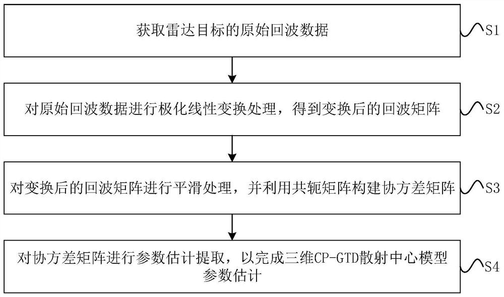
[0046] See figure 1 , figure 1 It is a schematic flowchart of a three-dimensional CP-GTD scattering center model parameter estimation method based on the improved 3D-P-ESPRIT algorithm provided by the embodiment of the present invention, specifically including the following steps:

[0047] S1: Obtain the original echo data of the radar target.

[0048] The total electromagnetic scattering response of the radar target in the high-frequency region can be considered as the sum of the electromagnetic scattering responses of several independent scattering centers on the radar line of sight. According to the geometrical diffraction theory, when the radar illuminates the target in a certain direction, the target's fully polarized three-dimensional The backscatter echo signal can be expressed as:

[0049]

[0050] in, represents the scattered echo data in the p-th polarization state, S i,p is the scattering intensity coefficient of the i-th scattering center under different po...

Embodiment 2

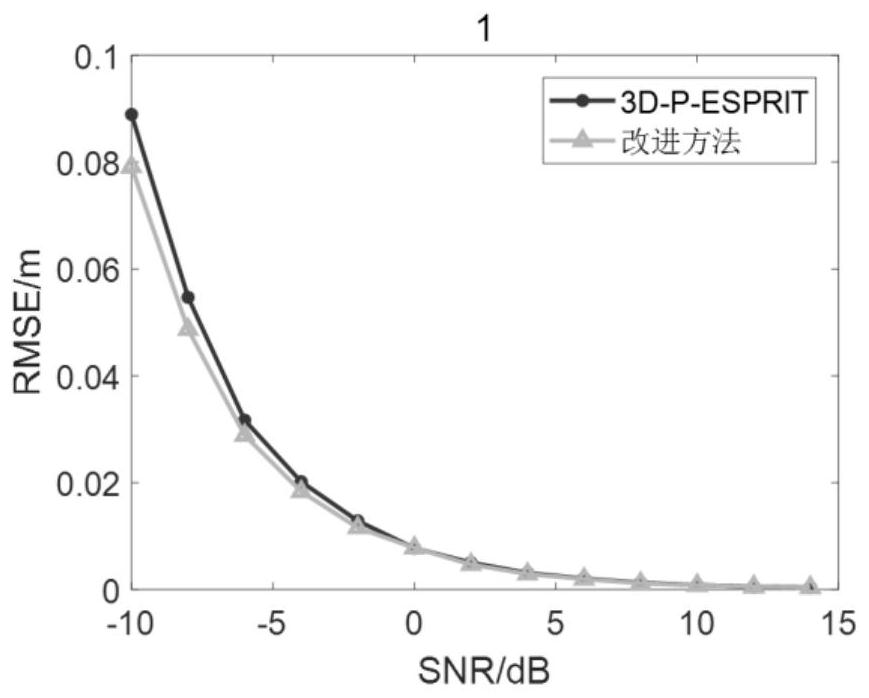
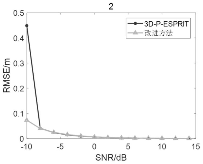
[0119] The beneficial effects of the present invention will be described in detail below through simulation experiments.

[0120] Simulation experiment one

[0121] 1.1 Experimental conditions:

[0122] In this experiment, the stepped frequency radar system is selected, and the initial frequency f of the radar is 0 =9.88GHz, the step frequency is 20MHz, the number of frequency samples is 20, the measurement range of radar azimuth angle is -0.5°~0.5°, the number of samples is 20, the measurement range of pitch angle is -0.5°~0.5°, the number of samples is 20 , the matrix beam parameters P, Q, and L are 13, and the target echo signal is composed of 5 scattering centers. The specific parameters of the scattering centers are set as shown in Table 1 below.

[0123] Scattering center parameters set in Table 1

[0124]

[0125] 1.2 Experiment content:

[0126] Select the SNR to change at equal intervals of -10dB to 20dB, use the improved method of the present invention and the...


PUM


Abstract

The invention discloses a three-dimensional CP-GTD scattering center model parameter estimation method based on an improved 3D-P-ESPRIT algorithm. The three-dimensional CP-GTD scattering center model parameter estimation method comprises the steps of obtaining original echo data of a radar target; performing polarization linear transformation processing on the original echo data to obtain a transformed echo matrix; carrying out decorrelation on the converted echo matrix, and constructing a covariance matrix by using a conjugate matrix; and performing parameter estimation extraction on the covariance matrix to complete three-dimensional CP-GTD scattering center model parameter estimation. Polarization linear transformation processing is carried out on echo data of a radar target, four sets of three-dimensional data are converted into three sets of three-dimensional data, the data storage amount and the calculated amount of follow-up decorrelation processing are reduced, conjugate information is introduced to construct a new data matrix, and the full-polarization covariance matrix is calculated by adopting a bidirectional spatial smoothing method, so that the observation matrix is utilized more fully, and the parameter estimation performance is improved.

Description

technical field [0001] The invention belongs to the technical field of array signal processing, and in particular relates to a parameter estimation method of a three-dimensional CP-GTD scattering center model based on an improved 3D-P-ESPRIT algorithm. Background technique [0002] With the increasingly fierce offensive and defensive confrontation in modern warfare, precision-guided weapons need to face a more complex battlefield environment, so higher requirements are placed on the ability of radar seekers in anti-jamming and target selection attacks. In the face of many different types of interference targets that may exist on the battlefield, the radar seeker needs to accurately guide the missile to select the target to be attacked among various targets, complete the attack task on the specific target, and achieve the greatest combat effectiveness. In order to improve the ability of precision guided weapons to detect and identify targets in complex battlefield environment...

Claims


Application Information

Patent Timeline
IPC IPC(8): G01S13/88G01S13/89G06F17/16
CPCG01S13/883G01S13/89G06F17/16Y02A90/10
Inventor 谢荣苏新璇冉磊刘峥王晶晶
Owner XIDIAN UNIV
Features
  • R&D
  • Intellectual Property
  • Life Sciences
  • Materials
  • Tech Scout
  • Unparalleled Data Quality
  • Higher Quality Content
  • 60% Fewer Hallucinations
Learn More