Split type DM inner layer oil seal part machining method

A part processing, split-type technology, which is applied in the field of oil seal processing, can solve the problems of clamping internal stress, lack of processing experience, and increase in the gap between the middle split surfaces, etc., to achieve stable processing methods, avoid clamping internal stress, and improve flatness Effect

Active Publication Date: 2021-10-26
CHONGQING JIANGJIN SHIPBUILDING IND
View PDF10 Cites 0 Cited by
  • Summary
  • Abstract
  • Description
  • Claims
  • Application Information

AI Technical Summary

Problems solved by technology

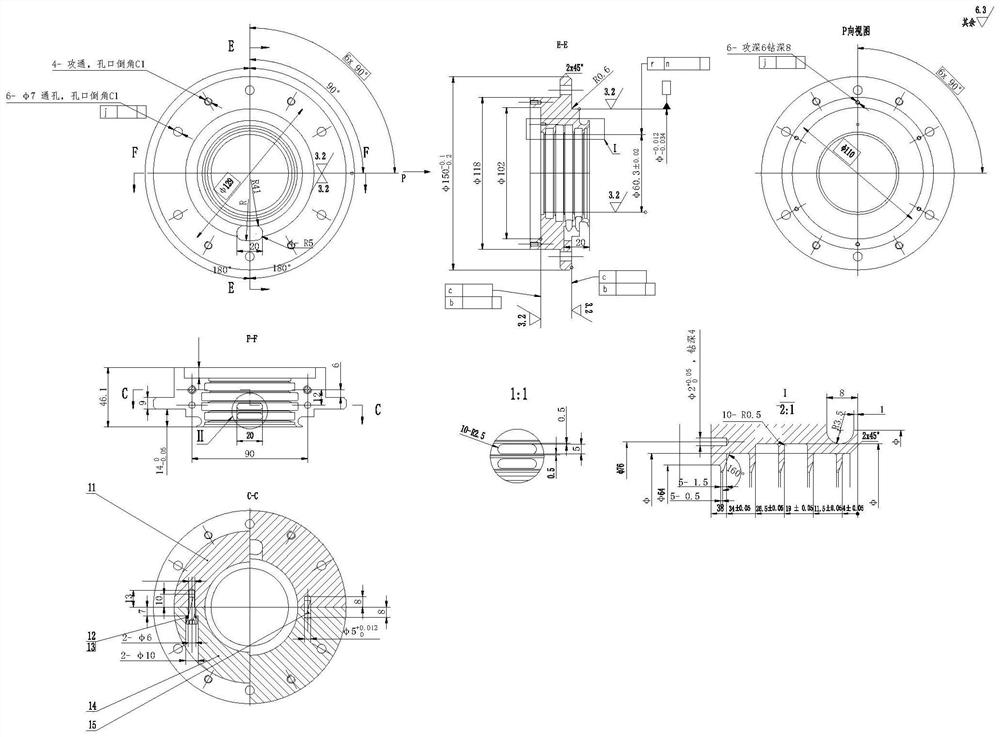
See Figure 2, the facets in this part are large, There is a high clearance requirement during assembly, which is difficult to meet, and the following problems occur during processing; 1. After the part is cut in half, the part deforms greatly, and the alignment requirement cannot be met in the natural state, and the technical requirements of the drawing cannot be met after processing.
2. Even if the assembly meets the technical requirements when the processing is completed, the parts will be deformed after a period of time, and the gap between the mid-sections will expand
3. There is no successful processing experience, which can be used for reference
[0005]1, 50 wire cutting process: After the part is cut into two halves by the wire cutting process, due to the stress concentration, the grinding positioning surface is deformed, resulting in failure in the subsequent grinding process. The alignment is smooth, and there is a large amount of internal force remaining inside the part, which is gradually released after the part is processed, causing the part to deform, resulting in a size that originally meets the requirements of the drawing, and the gap between the middle facets increases, etc.
[0006] 2.60 Grinding process: Before processing, it is necessary to find 4 points on the median surface, and the runout is required to be within 0.05mm. Due to the processing of the previous process, the positioning surface is ground It is not flat and cannot meet the requirements in the natural state. Forcibly knocking the part will cause internal stress in the clamping. After the processing is completed and the fixture is removed, the part cannot meet the gap between the mid-section and less than 0.02mm in the natural state.

Method used


Image

  • Split type DM inner layer oil seal part machining method
  • Split type DM inner layer oil seal part machining method
  • Split type DM inner layer oil seal part machining method

Examples


Embodiment Construction

[0064] Theoretical basis

[0065] a. After the part is cut in half, there will be a large amount of residual stress inside the part, which will cause the part to deform with the release of internal stress after the part is processed, so that the mid-plane gap of the part will increase and the size, Form and position tolerances and other out-of-tolerance.

[0066] b. After the part is cut in half, add a heat treatment process to anneal the part to release the stress inside the part, but the release of stress will cause the deformation of the positioning surface, making the positioning surface uneven during grinding. is not meeting the requirements.

[0067] c. After the internal stress of the positioning surface is released, a certain deformation will occur, resulting in the flatness of the positioning surface not meeting the requirements. Before machining, the part needs to be clamped based on the positioning surface, and the runout of the centering surface should not exceed...


PUM


Abstract

The invention discloses a split type DM inner layer oil seal part machining method. The machining precision is higher. The invention discloses a split type DM inner layer oil seal part machining method comprises the following working procedures that 10, a center hole of a workpiece is drilled and roughly turned; 20, heat treatment is conducted; 30, rough turning is conducted; 40, rough turning is conducted; 50, the workpiece is cut into two halves; 60, stress removing is conducted; 70, the positioning face is milled to be flat and used for grinding and clamping; 80, the positioning face is flattened; 90, four symmetrical points in the four directions of a split are aligned, and the split is ground out; 100, a connecting hole in the split of the workpiece is milled; 110, a chambering platform for a connection hole is milled; 120, chambering is conducted, an orifice is chamfered, the connecting hole is tapped, and the two halves are combined and assembled; 130, the small end and the outer circle of the workpiece are subjected to semi-finish turning; 140, the large end of the workpiece and the small-diameter section of a stepped hole are subjected to finish turning; 150, the small end and the stepped hole of the workpiece are subjected to the finish turning; 160, digital drilling is carried out; 170, digital drilling is conducted; 180, clamping is conducted; 190, digital drilling is carried out; and 200, clamping is conducted.

Description

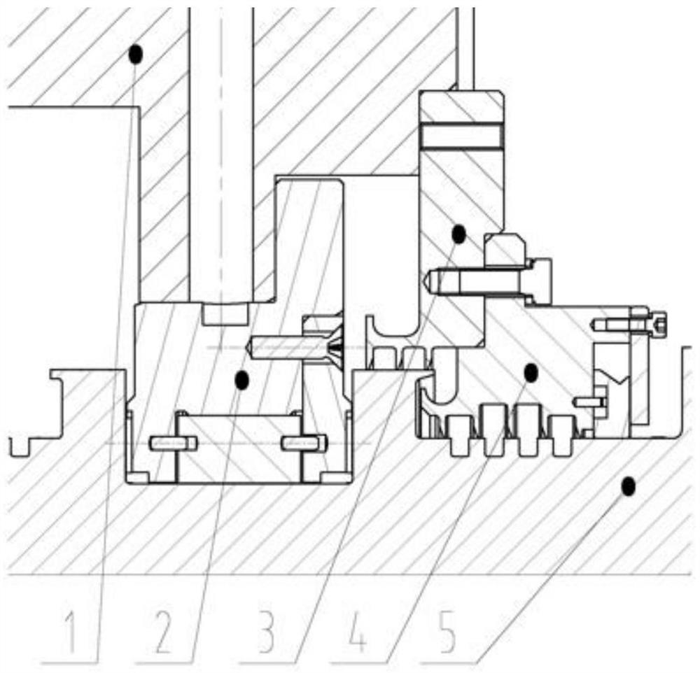
technical field [0001] The invention relates to the technical field of oil seal processing, in particular to a split-type DM inner layer oil seal part processing method. Background technique [0002] DM inner layer oil seal 1 is the core component of this type of compressor product, key parts, such as figure 1 As shown, this part is installed on the left end of the rotor. There are high requirements for assembly and cooperation between this part and the surrounding parts, especially the strict requirements for the clearance with the main shaft, so as to meet the sealing needs of the high-speed operation of the machine. The surface clearance also has higher requirements to avoid lubricating oil leakage during work. If the sealing performance is not good, the oil film will be uneven when the machine is running, which may cause the rotor sleeve to collide in severe cases. See figure 2 , the split face of this part is large, and there is a high clearance requirement during as...

Claims


Application Information

Patent Timeline
Patent Type & Authority Applications(China)
IPC IPC(8): B23P15/00
CPCB23P15/00
Inventor 李晟林周德贵鲁建于张德金周存高张怡江涛姚元润
Owner CHONGQING JIANGJIN SHIPBUILDING IND
Why Eureka
Try Eureka