


Quick Research
Generate reliable direction feasibility study reports for your R&D in just a few steps.

Technical Q&A
Discover and master advanced knowledge NOW. Basics, ideas, possibilities, all at once.

Find Solutions
As an expert in R&D theories, this can generate solutions to your technical problems instantly.

Evaluate Feasibility
Analyze your overall solution with one click, know your potential R&D risks in advance.

Monitor Landscape
Get weekly tech updates, stay abreast of the latest tech innovations and key insights.
Assembly type lamp strip suspended ceiling edge closing structure and installation method thereof
A prefabricated and light strip technology, which is applied in ceilings, building components, lighting devices, etc., can solve the problems of troublesome installation process, short service life, insufficient cooperation between quick-installed ceiling and wall, etc., and achieve high installation efficiency and structural simple effect
- Summary
- Abstract
- Description
- Claims
- Application Information
AI Technical Summary
Problems solved by technology
Method used
Image

Examples
Embodiment 1
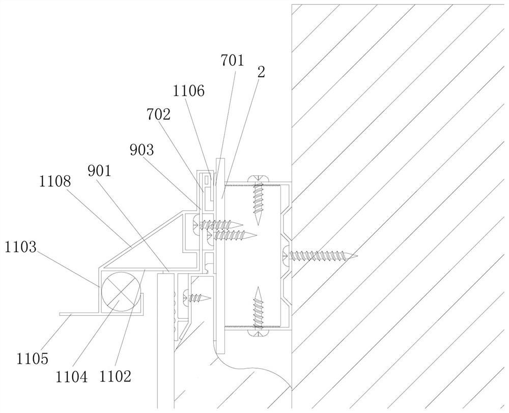
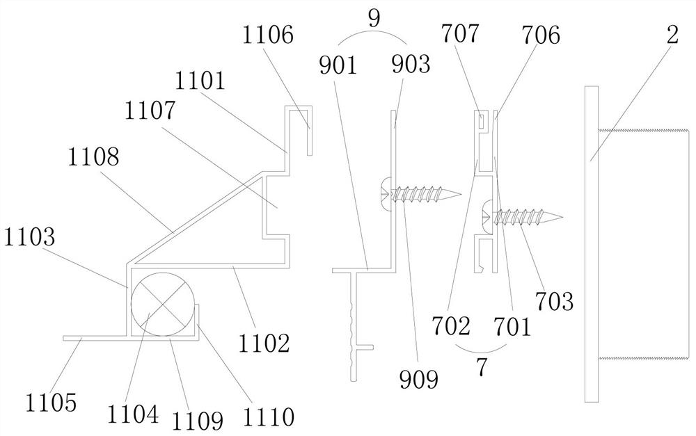
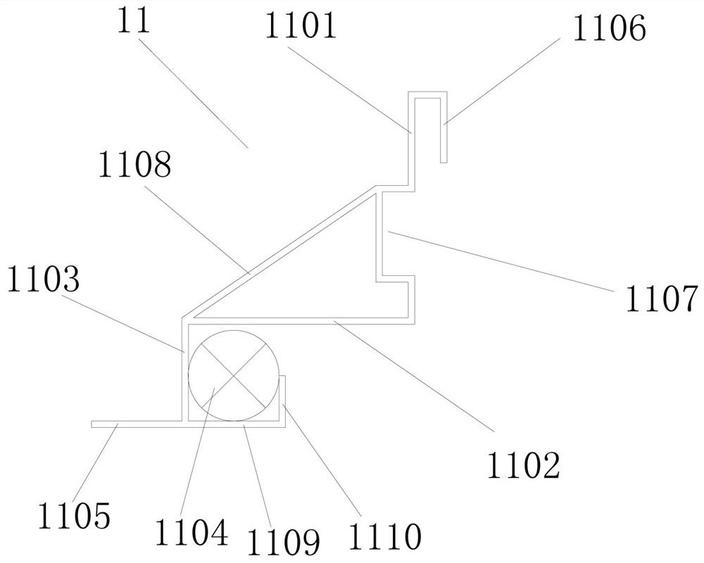
[0037] Embodiment one: if Figures 1 to 3As shown, it is only one of the embodiments of the present invention, a prefabricated light strip ceiling edge structure, including a leveling piece 2 arranged on the wall, and the leveling piece 2 is set far away from the wall The connecting piece 7 on one side of the connecting piece 7, the hanging piece 9 arranged on the side of the connecting piece 7 away from the leveling piece 2, and the light strip piece 11 set on the hanging piece 9, the connecting piece 7 includes a connecting bottom plate 701 and an upwardly extending first clamping plate 702 arranged on the side of the connecting bottom plate 701 away from the leveling member 2, and the hanging member 9 includes a The fixing plate 903 on the side away from the connecting bottom plate 701 and the horizontal mounting plate 901 on the side of the fixing plate 903 away from the first clamping plate 702, the light strip 11 includes The light strip vertical plate 1101 on the side ...
Embodiment 2
[0047] Embodiment two, still as Figures 1 to 3 As shown, it is only one of the embodiments of the present invention. On the basis of the first embodiment, in the edge-receiving structure of the assembled light strip ceiling of the present invention, the connecting bottom plate 701 is provided with a 2 connected with the sixth screw 704; the fixing plate 903 is provided with a seventh screw 909 for connecting with the leveling member 2. Here, the sixth screw is inserted through the connecting bottom plate into the leveling piece to complete the installation of the connecting piece; the seventh screw is sequentially inserted through the fixing plate and the connecting bottom plate into the leveling piece to complete the installation of the hanging piece. It should be noted that the seventh screw 909 will go through the connection base plate.
[0048] Certainly, the light strip riser 1101 is provided with a screw groove 1107 recessed away from the fixing plate 903; At this tim...
Embodiment 3
[0054] Embodiment three, such as Figure 4 As shown, the present invention also provides an installation method of a prefabricated light strip ceiling edge structure in all the above-mentioned embodiments, including the following steps:
[0055] S1: Install the leveling piece on the wall;
[0056] S2: Install the connecting piece on the side of the leveling piece away from the wall, so that the first clamping plate of the connecting piece is located on the side of the connecting bottom plate away from the leveling piece, and the first clamping plate extends upward;
[0057] S3: Install the hanging piece on the side of the connecting piece away from the leveling piece, so that the hanging plate of the hanging piece is located on the side of the fixing plate away from the first clamping plate and extends horizontally away from the wall;
[0058] S4: Install the light strip part to the hanging part, so that the vertical plate of the light strip is in contact with the side of the...
PUM
 Abstract
Description
Claims
Application Information
 - R&D Engineer
- R&D Manager
- IP Professional
- Industry Leading Data Capabilities
- Powerful AI technology
- Patent DNA Extraction
Browse by: Latest US Patents, China's latest patents, Technical Efficacy Thesaurus, Application Domain, Technology Topic, Popular Technical Reports.
© 2024 PatSnap. All rights reserved.Legal|Privacy policy|Modern Slavery Act Transparency Statement|Sitemap|About US| Contact US: help@patsnap.com