Method for designing spacer bush of rod end spherical hinge

A design method and spacer technology, applied in the field of shock absorption of elastic rubber parts, can solve the problems of high product cost, very high precision requirements, and affecting fatigue resistance, and achieve long life, simplified operation process, and good molding effects

Active Publication Date: 2021-10-26
ZHUZHOU TIMES NEW MATERIALS TECH
View PDF10 Cites 0 Cited by
  • Summary
  • Abstract
  • Description
  • Claims
  • Application Information

AI Technical Summary

Problems solved by technology

[0004] 1. The end face of the spacer is a conventional structure. Due to space constraints, the thickness of the spacer in the multi-layer rubber structure is usually very small, which makes the spacer easily deformed and difficult to position stably in the mold, which makes the distribution of the spacers in the finished product uneven. Average, affecting fatigue resistance, product life cannot be guaranteed
[0005] 2. With the existing design, when the radial load is large, due to the problem of the force angle, the product is still prone to poor fatigue resistance and product damage.
[0006] In view of the problem that the spacer is difficult to be positioned stably in the mold, in the prior art, the end of the spacer is usually set as figure 1 In the form of the rectangular end C on the right side of the dotted line D, the upper end face 7, the lower end face 10 and the side end face 8 of the rectangular end C are used for surface contact positioning with the mold between the end of the spacer and the mold. This method requires very high precision between the mold and the metal spacer, the tolerance of the spacer is poor, and the product cost is high

Method used


Image

  • Method for designing spacer bush of rod end spherical hinge
  • Method for designing spacer bush of rod end spherical hinge
  • Method for designing spacer bush of rod end spherical hinge

Examples


Embodiment 1

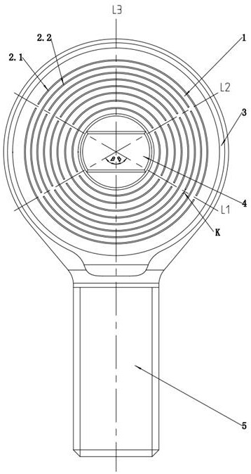
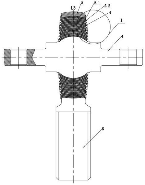
[0040] This example is attached Figure 2-6 As shown, a spacer design method for a rod-end ball joint, the above-mentioned rod-end ball joint includes a casing 3, a mandrel 4, a rubber layer 1 and a rod portion 5, the rubber layer 1 is located between the casing 3 and the mandrel 4, and the casing A rod portion 5 is arranged on the top, and the rod portion 5 is a threaded handle. Such as image 3 As shown, a multi-layer spacer is set in the rubber layer 1, and the multi-layer spacer divides the rubber layer 1 into a multi-layer structure; as figure 2 with Figure 5 As shown, the upper side 2.6 of the spacer, the lower side 2.7 of the spacer and the end face 2.5 of the spacer are set on the spacer, one end of the end face 2.5 of the spacer is connected with the upper side 2.6 of the spacer, and the end face 2.5 of the spacer is opposite to the upper side of the spacer. The other end of the side 2.6 is connected with the lower side 2.7 of the spacer, the upper side 2.6 of the ...

Embodiment 2

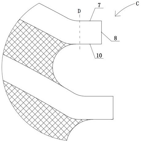
[0052] This example is attached Figure 7-9 As shown, the difference between Embodiment 2 and Embodiment 1 is that the spacer has 9 layers, that is, the rubber layer 1 is divided into 10 layers; the upper side 2.6 of the spacer is set as an arc surface, and the end surface 2.5 of the spacer is facing the inside of the ball joint. Set obliquely, the intersection of the upper side surface 2.6 of the spacer and the end surface 2.5 of the spacer forms a tip B1, and the point contact between the tip B1 and the mold is used to position the spacer axially during the vulcanization process; the end surface 2.5 of the spacer set obliquely and The intersection point B1 of the upper side 2.6 of the spacer and the mold 9 are positioned in point contact.


PUM

PropertyMeasurementUnit
Widthaaaaaaaaaa

Abstract

The invention relates to the field of damping of elastic rubber parts, and particularly relates to a method for designing a spacer bush of a rod end spherical hinge. The rod end spherical hinge comprises an outer sleeve, a mandrel and a rubber layer, the spacer bush is arranged in the rubber layer, the spacer bush is provided with a spacer bush upper side surface, a spacer bush lower side surface and a spacer bush end surface, one end of the spacer bush end surface is connected with the spacer bush upper side surface, the other end, opposite to the upper side surface of the spacer bush, of the spacer bush end surface is connected with the spacer bush lower side surface, a tip B1 is formed between the spacer bush end surface and the spacer bush upper side surface, the tip B1 between the spacer bush upper side surface and the spacer bush end surface is in point contact with a mold, the spacer bush is axially located in the vulcanization process by adopting point contact between the tip B1 and the mold, and the requirement on the tolerance of the spacer bush is reduced.

Description

technical field [0001] The invention relates to a design method for a spacer sleeve of a rod-end ball joint, and belongs to the technical field of shock absorption of elastic rubber parts. Background technique [0002] The rod end ball joint is an important shock-absorbing connection element, which is mostly used in trains, high-speed rail, automobiles, ships or airplanes. When the body is subjected to complex load conditions such as radial, torsion and deflection, the deformation of the rod end ball joint is used to bear Deviated torsion angle and radial load to prevent the body from rolling over during operation. The current rod end ball joint generally adopts a single-layer rubber joint form of a metal jacket-single-layer rubber layer-metal inner sleeve or a pure metal joint form; the radial stiffness of the single-layer rubber joint is small, and can only bear small radial loads. The anti-bias torsional load capacity is poor. Because the rubber layer is an integral stru...

Claims


Application Information

Patent Timeline
IPC IPC(8): F16F1/40F16C11/08G06F30/17
CPCF16F1/403F16C11/083G06F30/17F16F2230/14F16F2230/40G06F2119/18G06F2119/04
Inventor 黄江彪谢长伟罗增冯万盛谭方
Owner ZHUZHOU TIMES NEW MATERIALS TECH
Why Eureka
Try Eureka