Medical flushing device for paralyzed patient nursing
A flushing device and technology for paralyzed patients, applied in medical transportation, applications, home appliances, etc., can solve the problems of inconvenient cleaning and nursing for paralyzed patients, cross-infection, etc., to increase the flushing effect, reduce splashing, and realize the effect of kinetic energy transmission
- Summary
- Abstract
- Description
- Claims
- Application Information
AI Technical Summary
Problems solved by technology
Method used
Image

Examples
Embodiment 1
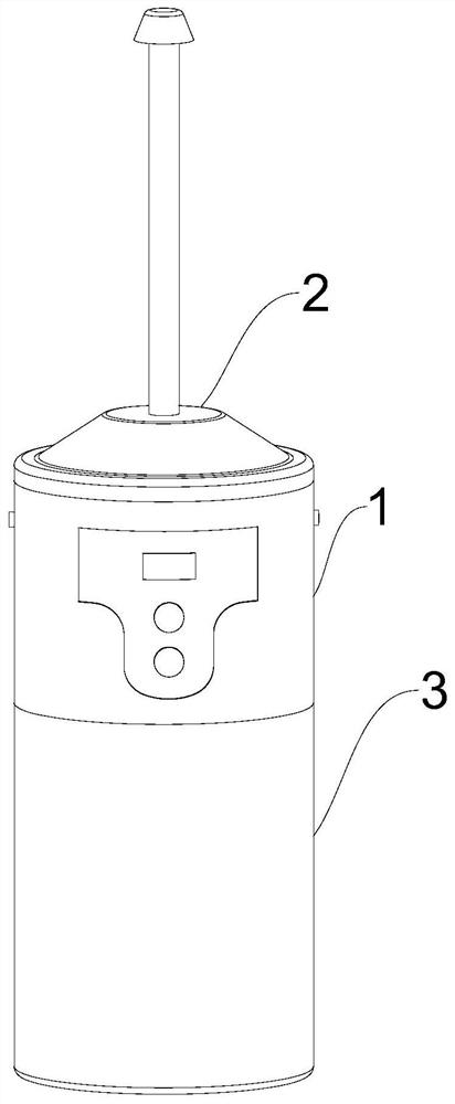
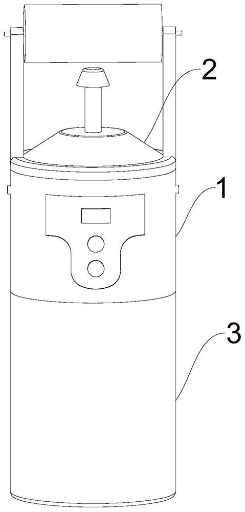
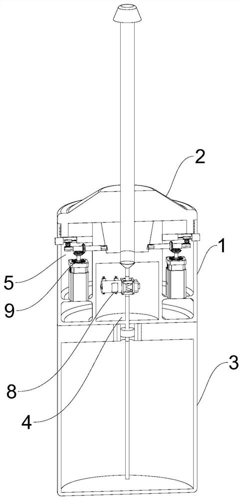
[0029] see Figure 1-4 , a medical flushing device for nursing care of paralyzed patients, comprising a tube body 1, a nozzle 2, and a water tank 3, the tube body 1 is threadedly connected with the nozzle 2 at the upper end and the water tank 3 at the lower end respectively, and a first cavity 4 is provided inside the tube body 1 , the annular limiting groove 5 and the fixing groove 6, the first cavity 4 has a cylindrical structure and is opened at the position below the middle of the pipe body 1, and the fixing groove 6 is an inverted frustum-shaped structure and is opened in the middle of the top surface of the pipe body 1 and downwards A first drainage pipe 7 communicating with the first cavity 4 is provided, a water pump 8 is provided inside the first cavity 4, and an annular position limiting groove 5 is provided around the outside of the first cavity 4 and the fixing groove 6. The drive assembly 9 is provided with a drive connection assembly 10 inside the spray head 2 . ...
Embodiment 2
[0034] see Figure 5-8 , based on Embodiment 1, the difference is that the driving assembly 9 includes a servo motor 901, and two servo motors 901 are symmetrically arranged inside the annular limiting groove 5, and the servo motor 901 is vertically arranged on its output shaft and socketed There is a bevel gear A902, a first rotating sleeve 903 is arranged horizontally above the servo motor 901, and a connecting hole 904 is provided on the pipe body 1 along the position of the first rotating sleeve 903 to connect the annular limiting groove 5 with the fixed groove 6, The first rotating sleeve 903 extends to the inside of the connecting hole 904 and rotates. The outer wall of the connecting hole 904 is sleeved with a bevel gear B905 that is vertically meshed with the bevel gear A902. The rod 906, both ends of the polygonal rod 906 pass through the first rotating sleeve 903 and extend to the outside thereof.
[0035] The driving assembly 9 also includes a control button 907, two...
Embodiment 3
[0038] see Figure 5 , 6 , 9, based on Embodiment 1-2, the difference is that the nozzle 2 includes a flushing nozzle 201, a scrubbing nozzle 202, and the middle part of the bottom of the flushing nozzle 201 and the scrubbing nozzle 202 is provided with a fixing block that is adapted to the fixing groove 6 206, the middle part of the flushing nozzle 201 and the scrubbing nozzle 202 is provided with a second drain pipe 203, and the top of the flushing nozzle 201 and the scrubbing nozzle 202 is provided with a first water spray pipe 204 communicated with the second drain pipe 203, and the scrubbing nozzle 202 includes a second The cavity 207 , the support rod 205 , and the second cavity 207 are arranged in a ring structure around the outside of the second drainage pipe 203 , and the bottom end of the support rod 205 is hollow and communicates with the second cavity 207 .
[0039] The driving connection assembly 10 includes a rotating shaft A1001. The two rotating shafts A1001 a...
PUM
 Abstract
Description
Claims
Application Information
PatSnap Eureka turns technology decisions into work you can execute. Powered by our Innovation Knowledge Graph, it runs expert workflows across engineering, life sciences, materials and intellectual property. Get your review-ready output in minutes.


