Device used for marking histological embedding box

A technique of embedding cassettes and histology, applied in printing, laser welding equipment, typewriters, etc., can solve the problems of wasting manpower, easily causing confusion, etc., achieving the effect of low cost, avoiding manpower tension, and easy to achieve.

Active Publication Date: 2021-10-29
南京精恒复合材料有限公司
View PDF11 Cites 0 Cited by
  • Summary
  • Abstract
  • Description
  • Claims
  • Application Information

AI Technical Summary

Problems solved by technology

[0003] The current device for marking embedding cassettes uses laser marking, which can prevent the inkjet method from being obliterated. When marking, it needs to be manually fed, which is a waste of manpower and easy to cause confusion.

Method used


Image

  • Device used for marking histological embedding box
  • Device used for marking histological embedding box
  • Device used for marking histological embedding box

Examples


Embodiment 1

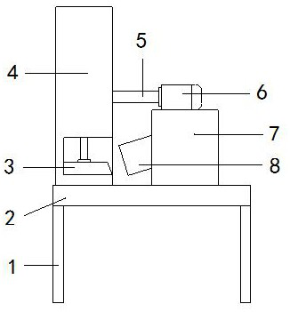
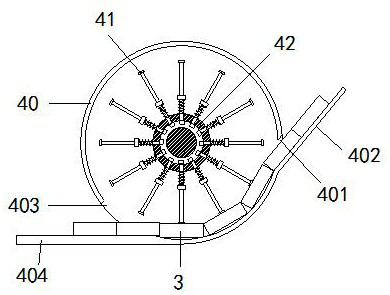
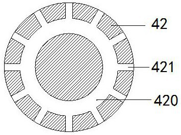
[0026] see Figure 1-4 , the present invention provides a technical scheme of a device for marking histological embedding cassettes: its structure includes a bracket 1, a workbench 2, an embedding cassette 3, a feeding device 4, a rotating shaft 5, a motor 6, a host machine 7, and a laser head 8 , the bottom of the workbench 2 is welded with a bracket 1, the workbench 2 is provided with a host 7, the side of the host 7 is connected with a laser head 8, the top of the host 7 is provided with a motor 6, and the motor 6 passes through Rotating shaft 5 is connected with feeding device 4, and described feeding device 4 is connected on the workbench 2 and is arranged on laser head 8 side, and described feeding device 4 comprises housing 40, elastic rod 41, rotating disk 42, and described housing 40 The bottom is connected to the workbench 2, a turntable 42 is installed in the middle of the casing 40, and evenly distributed elastic rods 41 are installed on the turntable 42, and an in...

Embodiment 2

[0029] see Figure 1-4 , the present invention provides a technical scheme of a device for marking histological embedding cassettes: its structure includes a bracket 1, a workbench 2, an embedding cassette 3, a feeding device 4, a rotating shaft 5, a motor 6, a host machine 7, and a laser head 8 , the bottom of the workbench 2 is welded with a bracket 1, the workbench 2 is provided with a host 7, the side of the host 7 is connected with a laser head 8, the top of the host 7 is provided with a motor 6, and the motor 6 passes through Rotating shaft 5 is connected with feeding device 4, and described feeding device 4 is connected on the workbench 2 and is arranged on laser head 8 side, and described feeding device 4 comprises housing 40, elastic rod 41, rotating disk 42, and described housing 40 The bottom is connected to the workbench 2, a turntable 42 is installed in the middle of the casing 40, and evenly distributed elastic rods 41 are installed on the turntable 42, and an in...


PUM


Abstract

The invention discloses a device used for marking a histological embedding box. The device structurally comprises a support, a workbench, the embedding box, a feeding device, a rotating shaft, a motor, a main machine and a laser head, the support is welded to the bottom of the workbench, the main machine is arranged on the workbench, the laser head is connected to the side face of the main machine, the motor is arranged above the main machine, the motor is connected with the feeding device through the rotating shaft, the feeding device is connected to the workbench and arranged on the side face of the laser head, the feeding device comprises a shell, elastic rods and a rotating disc, the bottom of the shell is connected to the workbench, the rotating disc is installed in the middle of the shell, the elastic rods which are evenly distributed are installed on the rotating disc, an inlet is formed in the left side of the shell, and a material guide plate is connected to the inlet. Through the design of the feeding structure, the embedding box can be sequentially and automatically sequenced to be marked, the phenomena of labor shortage and tearing hurry caused by manual feeding are avoided, and the feeding structure is simple, low in cost and easy to implement.

Description

technical field [0001] The invention relates to the field of surface marking devices, in particular to a device for marking histological embedding cassettes. Background technique [0002] A common embedding cassette comprises a main container unit and a lid, the main unit of an embedding cassette, usually made of plastic material, comprises a rectangular base with sides set away from its perimeter, delimiting the space for holding the sample , the lid encloses the sample in the holding chamber, one of the sides, actually one side of the box, has a sloped surface for marking, in fact each box must be marked with the patient's name of the hospital ward from which the sample was collected Detailed identifying information, and any other information that allows this information to be correlated with the results of the sample analysis, the patient was admitted on the day the sample was taken. [0003] The current device for marking embedding cassettes uses laser marking, which ca...

Claims


Application Information

Patent Timeline
Patent Type & Authority Applications(China)
IPC IPC(8): B23K26/362B23K26/70B41J2/435B41J3/407
CPCB23K26/362B23K26/702B41J2/435B41J3/407
Inventor 徐小燕
Owner 南京精恒复合材料有限公司
Why Eureka
Try Eureka