A kind of metal cutting fluid repeatedly used circulating flow purification equipment

A metal cutting fluid, circulating flow technology, applied in metal processing equipment, metal processing machinery parts, maintenance and safety accessories, etc., can solve problems such as reducing the operating space of cutting devices, cumbersome operation of recovering cutting fluid, and inability to match the collecting ends. , to achieve the effect of convenient recycling, preventing splashes and speeding up recycling efficiency

Active Publication Date: 2022-08-05
YINGTAN HEXING FIBER COMM COMPONENTS
View PDF1 Cites 0 Cited by
  • Summary
  • Abstract
  • Description
  • Claims
  • Application Information

AI Technical Summary

Problems solved by technology

[0005] The purpose of the present invention is to provide a metal cutting fluid recycling circulation purification equipment to solve the problem that the existing metal cutting fluid recycling circulation purification equipment proposed in the above background technology, in the process of its use, the liquid collection end is not convenient The matching of different cutting devices makes the operation of recycling cutting fluid cumbersome. At the same time, the high-pressure sprayed cutting fluid is easy to hit the surface of the collection tank and splash a lot of water. It is necessary to place a large baffle next to the nozzle for blocking to completely collect the cutting fluid. Liquid, larger baffles reduce the operating space of the cutting device

Method used


Image

  • A kind of metal cutting fluid repeatedly used circulating flow purification equipment
  • A kind of metal cutting fluid repeatedly used circulating flow purification equipment
  • A kind of metal cutting fluid repeatedly used circulating flow purification equipment

Examples


Embodiment 1

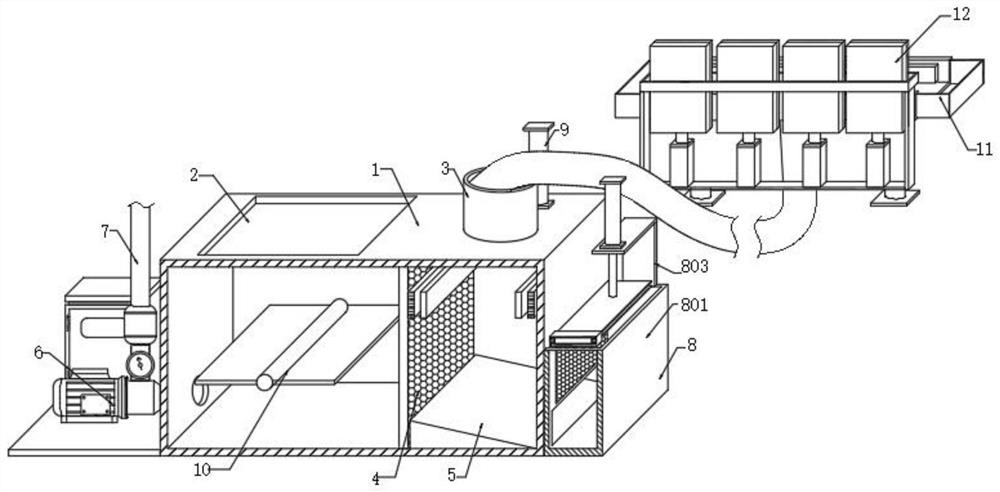
[0034] see Figure 7-Figure 8 In the embodiment of the present invention, the feeding component 11 includes a collecting tank 1101, two sides of the collecting tank 1101 are sleeved with telescopic grooves 1102, two sides of the inner wall of the collecting tank 1101 are fixed with magnets 1103, and the lower end of the collecting tank 1101 is fixed with a A connecting pipe 1104 is connected to the input end of the liquid inlet pipe 3, a second chute 1105 is fixed at the lower end of the collecting chute 1101, and the inner cavity of the second chute 1105 is sleeved and inserted with a second sliding block 1106, and the lower part of the second sliding block 1106 A rotating shaft 1107 is fixed on the end face, a third cylinder 1108 is fixed at the rotating end of the rotating shaft 1107, a backing plate 1109 is fixed at the lower end of the third cylinder 1108, and the expansion groove 1102 can be pulled out from both sides of the collecting groove 1101 to increase the aggregat...

Embodiment 2

[0036] see Figure 9-Figure 11 The difference from Embodiment 1 is that the splash-proof assembly 12 includes an annular plate 1201 fixed on the upper end of the collecting tank 1101, a mounting plate 1202 is fixed at the lower end of one side of the annular plate 1201, and a number of fourth The cylinder 1203, the upper ends of several fourth cylinders 1203 are fixed with a shielding plate 1204 sleeved with the inner cavity of the annular plate 1201, the surface of the shielding plate 1204 is fixed with a sponge 1205, the upper end of the shielding plate 1204 is fixed with an infrared sensor module 1206, and the annular plate 1201 Two connecting blocks 1207 are fixed on the upper end, a sleeve rod 1208 is fixed between the two connecting blocks 1207, a shovel plate 1209 is sleeved on the surface of the sleeve rod 1208, and a torsion spring 1210 is fixed between the shovel plate 1209 and the connecting block 1207, and the shovel plate 1209 can always keep pressing and fit on t...

Embodiment 3

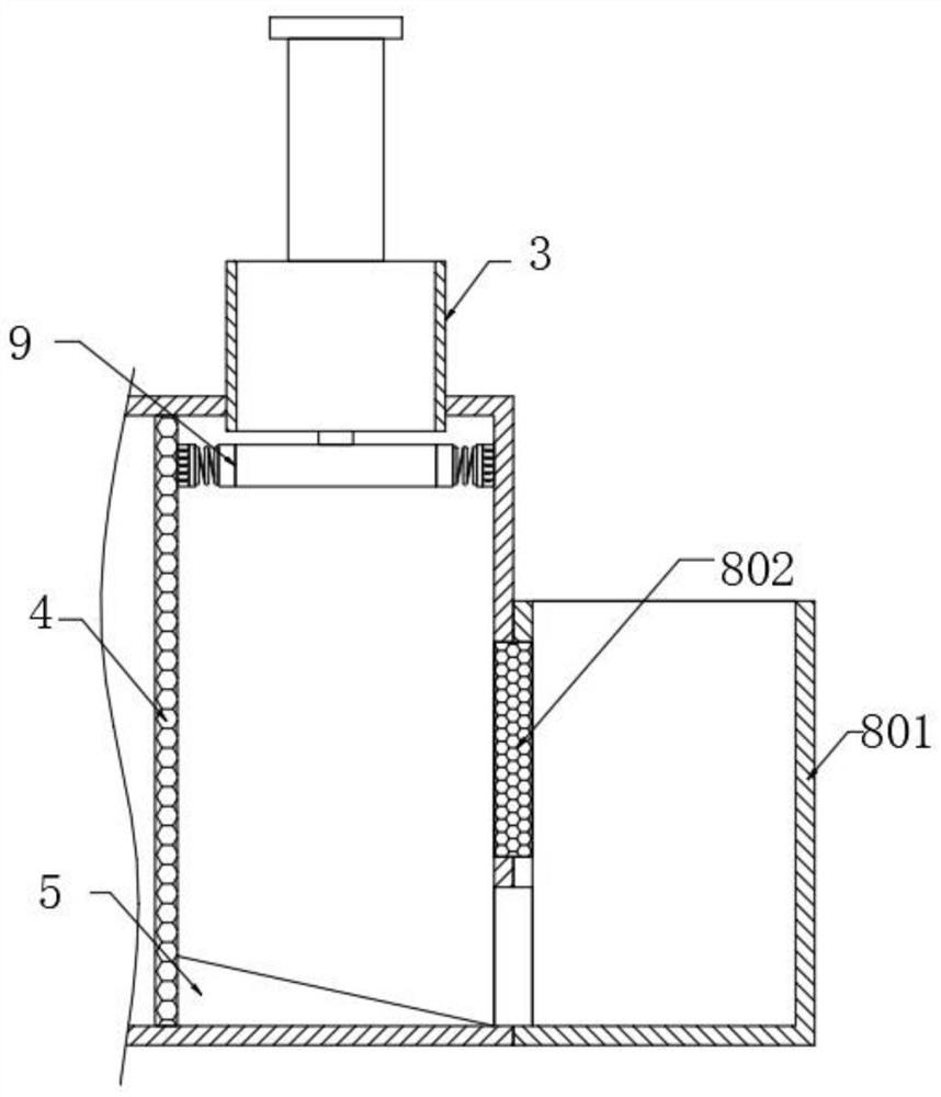
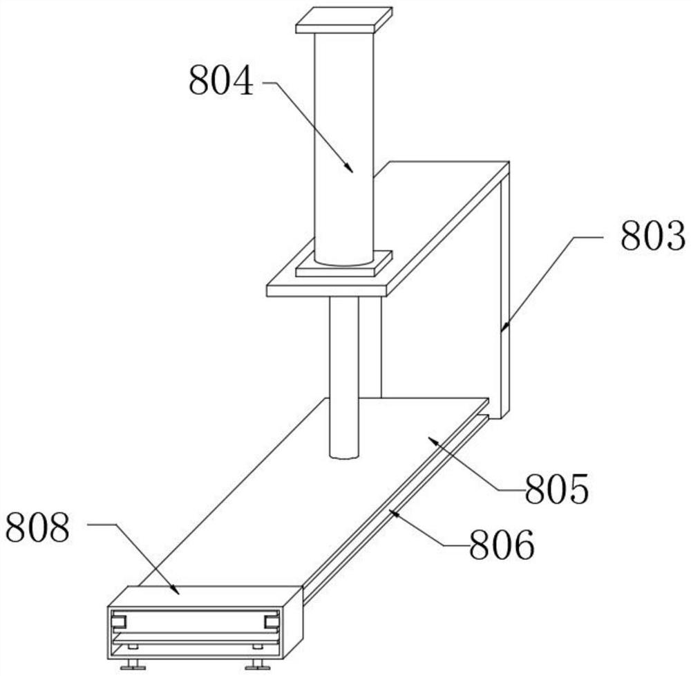
[0038] see Figure 2-Figure 4 , The difference from Embodiment 1 is that the purification assembly 8 includes: a dirt storage tank 801 fixed on the surface of the box body 1, a filter screen 802 is fitted between the dirt storage tank 801 and the box body 1; The support plate 803 on the upper end face of the 801, the top end of the support plate 803 is fitted with a first cylinder 804, the lower output end of the first cylinder 804 is fixed with an electromagnetic plate 805, and the electromagnetic plate 805 is provided with a first chute 806 on both sides. The inner cavity of the groove 806 is sleeved with a first sliding block 807. The surface of the two first sliding blocks 807 is fixed with a sleeve plate 808 that is sleeved with the electromagnetic plate 805. The lower end of the sleeve plate 808 is threadedly engaged with a bolt 809, and the bolt 809 is close to the sleeve. One end of the center line of the plate 808 is rotated and installed with a scraper 810 through a ...


PUM


Abstract

The invention discloses a recycling of a metal cutting fluid with a circular flow purification equipment, which is characterized by: boxes; adding liquid ports on one side of the upper ends of the box,There is a liquid pipe, which is fixed with a filter partition in the internal cavity of the box. The side of the filter partition is installed with a fixed sewage plate with the internal cavity of the box.The loop pump output end is fixed with a drainage pipe; the purification component is located in the case of the box from the side of the circulating pump away.This device can recycle the cutting fluid directly from different processing equipment for recycling and purification. Through the scaling size collection groove, it can match the drainage end of the cutting device of different models.The solution to the existing purification device needs to be used in advance to collect the cutting fluid recycling, and then pour it into the method of purifying equipment, making the recovery of metal cutting solution more convenient.

Description

technical field [0001] The invention relates to the field of cutting fluid circulation equipment, in particular to a circulating flow purification equipment for repeated use of metal cutting fluid. Background technique [0002] Cutting fluid is an industrial fluid used to cool and lubricate cutting tools and workpieces in the process of metal cutting and grinding. Cooling performance, lubricating performance, anti-rust performance, degreasing and cleaning function, anti-corrosion function, easy to dilute, it has the characteristics of good cooling, cleaning, rust prevention, etc. It has the characteristics of corrosion and no pollution to the environment. In its cutting operation, the cutting fluid is circulated through circulating equipment. [0003] The existing metal cutting fluid repeatedly uses the circulating flow purification equipment. In the process of its use, the liquid collecting end cannot be easily matched with different cutting devices, which makes the operat...

Claims


Application Information

Patent Timeline
Patent Type & Authority Patents(China)
IPC IPC(8): C10M175/00B23Q11/10
CPCC10M175/00C10M175/0066B23Q11/1069
Inventor 龚洋洋
Owner YINGTAN HEXING FIBER COMM COMPONENTS
Why Eureka
Try Eureka