
Low-pressure turbine dynamic balance system, dynamic balance tool and dynamic balance method

A low-pressure turbine and tooling technology, applied in engine components, machines/engines, blade support components, etc., can solve problems such as the inability to directly support the horizontal balancing machine, and the inability to adapt to the dynamic balance of the low-pressure turbine rotor, so as to improve the quality of the balancing process. , the effect of reducing the impact, eliminating the impact

Pending Publication Date: 2021-10-29
AECC COMML AIRCRAFT ENGINE CO LTD
View PDF10 Cites 0 Cited by
  • Summary
  • Abstract
  • Description
  • Claims
  • Application Information

AI Technical Summary

Problems solved by technology

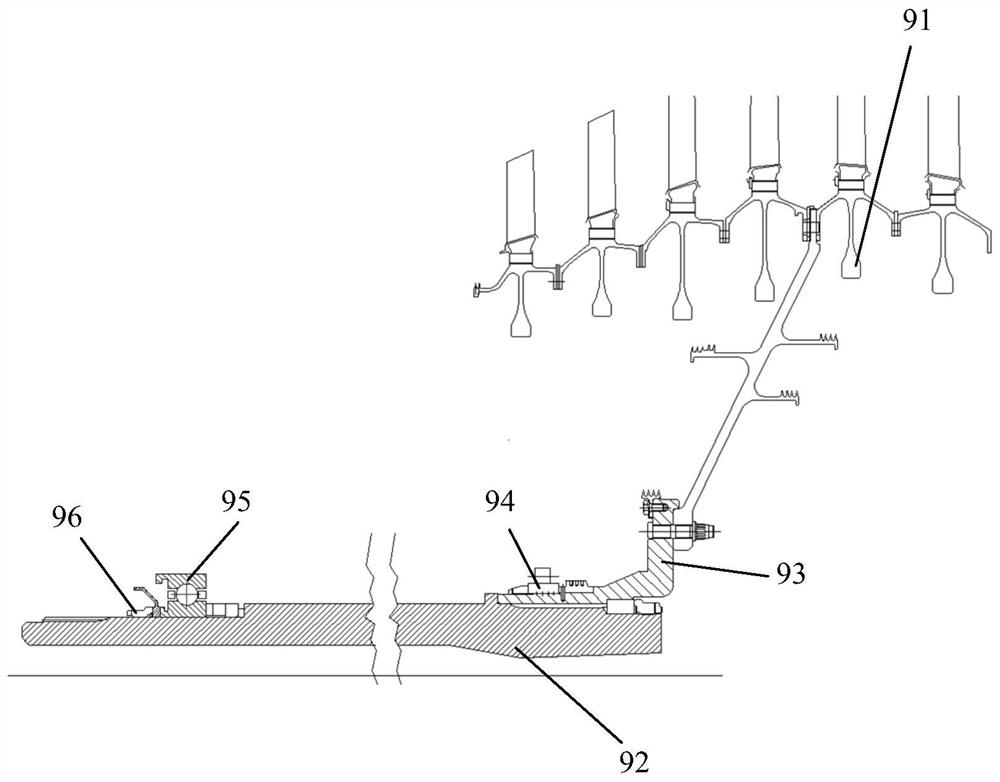
[0004] However if figure 1 The two fulcrums of the compressor turbine rotor shown in are located at the front end of the rotor, and the rear fulcrum is still in the disk cavity of the turbine disk, which cannot be directly supported on the horizontal balancing machine. The existing simply supported scheme cannot adapt to the low pressure of this type of structure. Dynamic Balancing of Turbine Rotors

Method used


Image

  • Low-pressure turbine dynamic balance system, dynamic balance tool and dynamic balance method
  • Low-pressure turbine dynamic balance system, dynamic balance tool and dynamic balance method
  • Low-pressure turbine dynamic balance system, dynamic balance tool and dynamic balance method

Examples


Embodiment Construction

[0042] A variety of different implementations or examples for implementing the described subject technical solutions are disclosed below. In order to simplify the disclosure, the following describes the specific examples of each element and arrangement, and of course, these are only examples, and are not intended to limit the protection scope of the present application. For example, the description that the first feature described later in the description is formed on or above the second feature may include an embodiment in which the first and second features are formed through direct contact, and may also include an embodiment in which the first and second features are formed between the first and second features. Embodiments of additional features such that there may be no direct relationship between the first and second features. Additionally, reference numerals and / or letters may be repeated in different instances in these disclosures. This repetition is for brevity and c...


PUM


Abstract

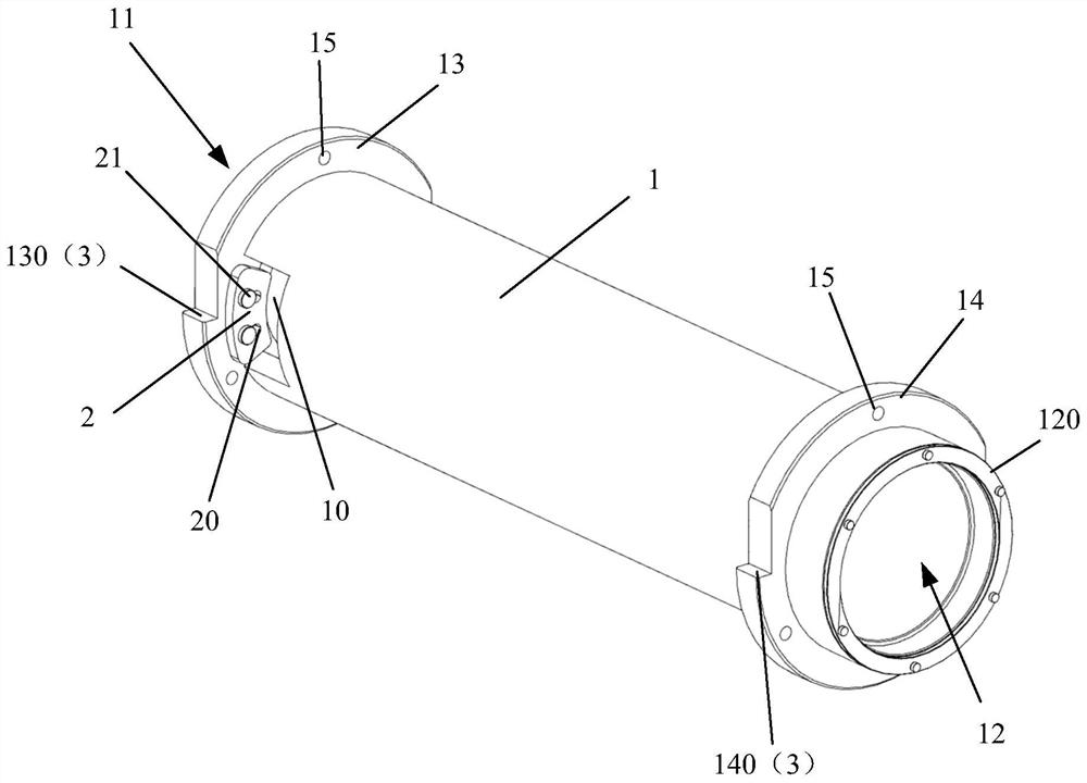
One purpose of the invention is to provide a low-pressure turbine dynamic balance tool, so that the influence of the balance tool on the dynamic balance of a low-pressure turbine rotor can be reduced while a rotor assembly is supported on a horizontal balancing machine. The other purpose of the invention is to provide a low-pressure turbine dynamic balance system. The invention further aims at providing a low-pressure turbine dynamic balance method. The low-pressure turbine dynamic balance system is adopted for carrying out dynamic balance on the rotor assembly. In order to achieve the purpose, the low-pressure turbine dynamic balance tool comprises an outer barrel, a baffle piece and two installation parts. The outer barrel is provided with a first open end and a second open end, at least one opening is formed in the barrel wall close to the first open end, and the end face of the second open end is provided with a limiting part extending towards the inner side; the baffle piece is arranged at the opening and can move in the radial direction of the outer barrel; and the two installation parts are arranged on the peripheral wall surface of the outer cylinder body corresponding to the positions of the balancing machine bearing bushes.

Description

technical field [0001] The invention relates to a low-pressure turbine dynamic balancing system, a dynamic balancing tool and a dynamic balancing method. Background technique [0002] Such as figure 1 A schematic diagram of an existing low-pressure turbine rotor is shown, which is composed of two sub-components, a turbine rotor assembly 91 and a turbine shaft 92. The turbine rotor assembly 91 is fixed on an adapter stub shaft 93 by threaded fasteners, and the adapter stub shaft 93 is fixed on the turbine shaft 92 by splines combined with a large nut compression mode. The turbine rotor assembly 91 is fixed on the engine by means of double fulcrum support, in which the rear bearing 94 is a rolling bearing, which is installed on the short transfer shaft and is located behind the disk cavity formed by the first-stage turbine disk; the front bearing 95 is a half-shaped inner ring The ball bearing is fixed on the front shoulder of the turbine shaft 92 by means of a compression n...

Claims


Application Information

Patent Timeline
IPC IPC(8): F01D25/28F01D25/00F01D5/02
CPCF01D25/285F01D25/00F01D5/027Y02E10/20
Inventor 胡一廷郑思凯史新宇杨波
Owner AECC COMML AIRCRAFT ENGINE CO LTD
Learn More