
A three-way catalytic converter anti-clogging structure

A catalytic converter and anti-clogging technology, used in engine components, machines/engines, internal combustion piston engines, etc., can solve problems such as easy clogging and affect service life, and achieve the effect of preventing clogging and reasonable structure design.

Active Publication Date: 2022-06-03
JILIN UNIV
View PDF28 Cites 0 Cited by
  • Summary
  • Abstract
  • Description
  • Claims
  • Application Information

AI Technical Summary

Problems solved by technology

[0003] The existing three-way catalytic converter has some shortcomings in the process of use, such as easy to block during use, which affects the service life. Therefore, we propose a new three-way catalytic converter anti-clogging structure to solve the above problems

Method used


Image

  • A three-way catalytic converter anti-clogging structure
  • A three-way catalytic converter anti-clogging structure
  • A three-way catalytic converter anti-clogging structure

Examples


Embodiment Construction

[0021] In order to make the above objects, features and advantages of the present invention more clearly understood, the specific embodiments of the present invention will be described in detail below with reference to the accompanying drawings.

[0022] Many specific details are set forth in the following description to facilitate a full understanding of the present invention, but the present invention can also be implemented in other ways different from those described herein, and those skilled in the art can do so without departing from the connotation of the present invention. Similar promotion, therefore, the present invention is not limited by the specific embodiments disclosed below.

[0023] Next, the present invention is described in detail with reference to the schematic diagrams. When describing the embodiments of the present invention in detail, for the convenience of explanation, the sectional views showing the device structure will not be partially enlarged accord...


PUM


Abstract

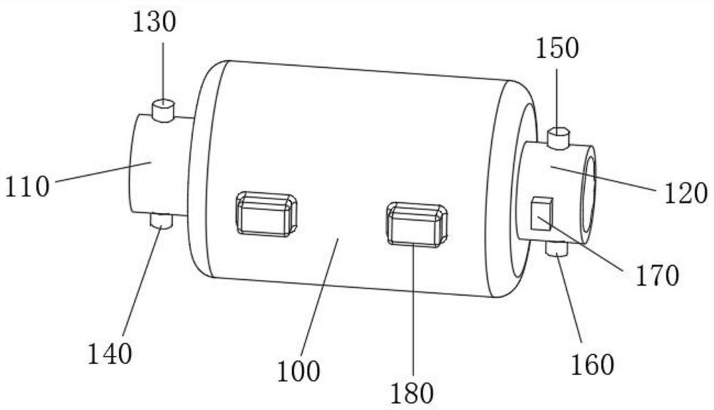
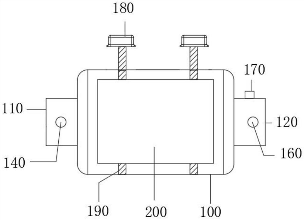
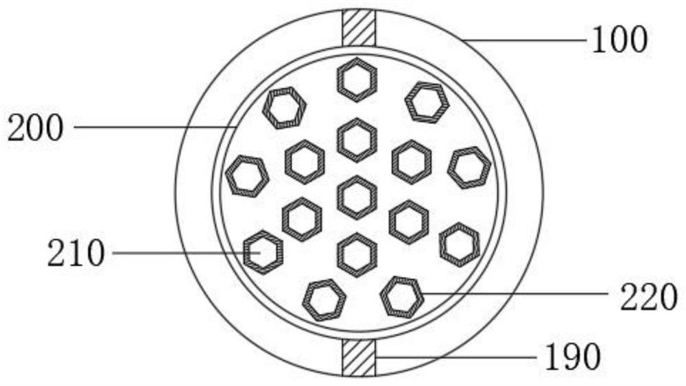
The invention belongs to the technical field of automobile exhaust emission, and specifically relates to an anti-clogging structure of a three-way catalytic converter, which includes a shell and a ceramic carrier. The shell includes a metal shell, and the inner wall of the metal shell is provided with an insulating interlayer. The inner side wall of the heat insulating interlayer is provided with an anti-corrosion coating, the left side of the housing is provided with an air inlet, and the top and bottom of the air inlet are respectively provided with a front pressure sensor and a front temperature sensor. The right side of the exhaust port is provided with an exhaust port, the top and bottom of the exhaust port are respectively provided with a rear pressure sensor and a rear temperature sensor, the front surface of the exhaust port is provided with a gas flow rate sensor, and the front surface of the housing A vibrating motor is provided, and a transmission rod is provided on the side wall of the inner cavity of the housing. Its structure is reasonable. During use, it is convenient to monitor the temperature and pressure of the intake air and the temperature and pressure of the exhaust gas. At the same time, the gas flow rate at the exhaust port can be detected. Prevent clogging.

Description

technical field [0001] The invention relates to the technical field of automobile exhaust emission, in particular to an anti-clogging structure of a three-way catalytic converter. Background technique [0002] Catalytic Converter (CatalyticConverter), also known as catalytic converter. The device is installed in the exhaust system of the car, and its role is to reduce most of the exhaust pollutants emitted by the engine. The three-way catalytic converter consists of a metal shell, a mesh bottom frame and a catalytic layer (containing precious metals such as platinum and rhodium), which can remove HC (hydrocarbons), CO (carbon monoxide) and NOx (nitrogen oxides) three 90% of the major pollutants (the so-called ternary refers to the chemical reaction that occurs when these three compounds are removed). When the exhaust gas passes through the purifier, the platinum catalyst promotes the oxidation of HC and CO to produce water vapor and carbon dioxide; the rhodium catalyst pro...

Claims


Application Information

Patent Timeline
Patent Type & Authority Patents(China)
IPC IPC(8): F01N3/28F01N9/00F01N11/00
CPCF01N3/28F01N3/2828F01N11/002F01N9/00F01N2260/04Y02T10/40
Inventor 杜秀达李梦莹田艳荣曾小华
Owner JILIN UNIV
Learn More