Engine label information visual detection system and method
A technology of visual inspection and label information, which is applied in the field of visual inspection, can solve problems such as low continuity of visual inspection, easy fatigue of employees, and difficulty in identification, and achieve the effects of reducing the operating rhythm of employees, improving the rate of production automation, and reducing transformation costs
- Summary
- Abstract
- Description
- Claims
- Application Information
AI Technical Summary
Problems solved by technology
Method used
Image
Examples
Embodiment 1
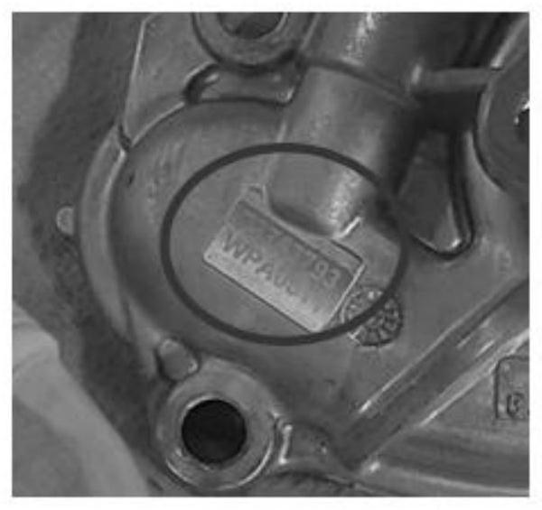
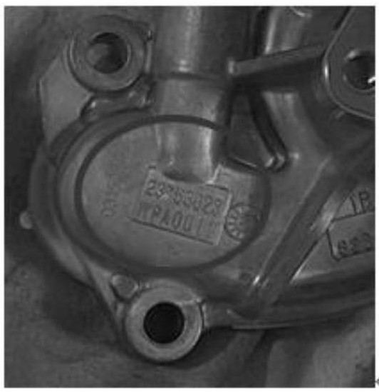
[0043] The error-proof operation process and detection process of water pump parts are as follows:
[0044] Step A: After the engine arrives at the station, the gear stop device on the track stops the engine, and RFID (radio frequency identification) identifies the engine model information;
[0045] Step B: the PLC device sends a station arrival signal to a certain holding register of the PLC device according to the arrival information of the engine;
[0046] Step C: The system software will read the value of the holding register on the PLC device in real time through the OPC communication protocol. If the value changes, it indicates that the engine has arrived, and the camera camera program is started to obtain a photo of the current engine parts
[0047] Step D: Detection process:
[0048] Step D1: Since the installation position of the engine water pump is fixed, and the position of the part identification is fixed, the upper, lower, left, and right coordinates of the iden...
Embodiment 2
[0056] The error-proof operation process and detection process of the piston assembly are as follows:
[0057] Step A: After the engine arrives at the station, the gear stop device on the track stops the engine, and RFID (radio frequency identification) identifies the engine model information;
[0058] Step B: According to the arrival information of the engine, the PLC equipment sends an arrival signal to a holding register of the PLC equipment. Different models send different signals, which can be freely defined;
[0059] Step C: the system reads the value of the register in real time through the OPC communication protocol. If the value changes, the camera program is triggered to start, and a current engine part photo is automatically obtained;
[0060] Step D: Detection process:
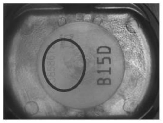
[0061] Step D1: There are four engine piston assemblies, and two cameras are required to take pictures, and the installation position of the engine piston assembly is fixed, and the position of th...
Embodiment 3
[0069] Figure 5 It is an engine part number visual inspection system according to an embodiment of the present invention, including an engine label 1, a camera bracket 2, an image acquisition module 3, an image processing identification module 4, an engine roller table 5 and a model information reading module (RFID) 6 .
[0070] Wherein, the image acquisition module 3 adopts an industrial camera.
[0071] Image 6 It is the software interface, the left side is the parameter setting, and the right side is the part photo display.
[0072] This scene is used to identify the part number information on the part label. The part number of the recognition result is displayed in the lower right corner, compared with the preset value, the result is correct, and the result is OK output to the PLC. The recognition results and comparison results are printed out on the software interface and saved for subsequent tracking of parts quality problems.
PUM
 Abstract
Description
Claims
Application Information
 - R&D
- Intellectual Property
- Life Sciences
- Materials
- Tech Scout
- Unparalleled Data Quality
- Higher Quality Content
- 60% Fewer Hallucinations
Browse by: Latest US Patents, China's latest patents, Technical Efficacy Thesaurus, Application Domain, Technology Topic, Popular Technical Reports.
© 2025 PatSnap. All rights reserved.Legal|Privacy policy|Modern Slavery Act Transparency Statement|Sitemap|About US| Contact US: help@patsnap.com


