A kind of bias circuit and power amplifier for power amplifier

A power amplifier and bias circuit technology, applied in the field of radio frequency/microwave, can solve the problems of large energy loss, inability to meet the ultra-broadband working requirements of the power amplifier, etc., and achieve the effect of increasing the gain

Active Publication Date: 2021-12-14
SHENZHEN CITY SIGLENT TECH
View PDF0 Cites 0 Cited by
  • Summary
  • Abstract
  • Description
  • Claims
  • Application Information

AI Technical Summary

Problems solved by technology

[0004] The present application provides a bias circuit for a power amplifier to solve the technical problem that the bias circuit of the power amplifier in the prior art has a large energy loss and cannot meet the ultra-wideband working requirements of the power amplifier

Method used


Image

  • A kind of bias circuit and power amplifier for power amplifier
  • A kind of bias circuit and power amplifier for power amplifier
  • A kind of bias circuit and power amplifier for power amplifier

Examples


Embodiment 1

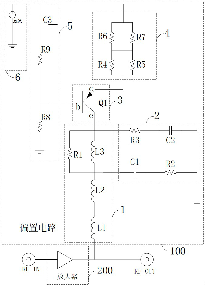
[0036] Please refer to image 3 , is a schematic circuit diagram of a bias circuit in an embodiment, including a bias circuit 100 and a power amplifier 200 . The bias circuit 100 is used to provide the power amplifier 100 with a quiescent operating current. The bias circuit 100 includes a bias connection terminal, a DC power connection terminal, a self-resonant circuit 1 , a decoupling filter circuit 2 , a triode circuit 3 , a power sharing circuit 4 and a work holding circuit 5 . The triode circuit 3 includes a triode Q1. The bias connection terminal is used for connecting with the output terminal of the power amplifier 200 , and the DC power connection terminal is used for the input of the DC power supply 6 . The self-resonant circuit 1 is respectively connected to the second pole connection and the bias connection terminal of the transistor Q1. The self-resonant circuit 1 is used to suppress the reverse flow of the AC signal output by the power amplifier 200, and also pr...

Embodiment 2

[0046] Please refer to Figure 4 It is a schematic structural diagram of a bias circuit board in another embodiment, the bias circuit board includes a bias circuit wiring area 10 . The bias circuit wiring area 10 is provided with a bias circuit, the bias circuit includes a bias connection terminal, a DC power connection terminal, a self-resonant circuit, a decoupling filter circuit, a transistor Q1, a power sharing circuit and a work holding circuit. Wherein, the bias connection terminal is used for electrically connecting with the output terminal of a power amplifier, and the bias circuit is used for providing static working current to the power amplifier. The DC power connector is used for the input of DC power. The self-resonant circuit is respectively connected to the second pole connection and the bias connection terminal of the transistor Q1. The self-resonant circuit is used to restrain the reverse flow of the AC signal output by the power amplifier, and also prevent ...


PUM


Abstract

The application discloses a bias circuit for a power amplifier. The bias circuit is used to provide a static operating current to the power amplifier. The bias circuit includes a bias connection terminal, a DC power supply connection terminal, a self-resonant circuit, and a decoupling filter circuit. , Transistor Q1, power sharing circuit and work holding circuit. The self-resonant circuit is used to curb the reverse flow of the AC signal output by the power amplifier, and also prevent the leakage of high-frequency signal energy. The decoupling filter circuit is used to reduce the Q value of the self-resonant circuit. The power sharing circuit is used to share the output power of the DC power supply. The work holding circuit is used to ensure the stable operation of the triode Q1, and then provide a stable quiescent working current to the power amplifier. Since the ultra-wideband bias circuit is realized through the triode amplifier circuit with a DC source, it can not only provide a normal operating voltage difference for the power amplifier, but also not bring too much device insertion loss to the power amplifier, so that the gain of the power amplifier can be obtained. improve.

Description

technical field [0001] The present invention relates to the field of radio frequency / microwave technology, in particular to a bias circuit and a power amplifier for a power amplifier. Background technique [0002] Power amplifiers are widely used in various wireless communication equipment and electronic systems. As an important part of wireless transmitters, various communication indicators need to meet strict requirements. With the promotion of 5G technology, the frequency bandwidth of power amplifiers has begun to receive close attention, and people are keen to design ultra-wideband power amplifiers with good performance. However, the performance of a power amplifier depends on the design of the bias circuit. The power amplifier needs to obtain energy from the DC power supply through the bias circuit to amplify the input signal. Therefore, the bias circuit becomes the key link in the design of the ultra-wide power amplifier. In the UWB power amplifier bias circuit, the ...

Claims


Application Information

Patent Timeline
Patent Type & Authority Patents(China)
IPC IPC(8): H03F1/48H03F3/195H03F3/213H03F3/22
CPCH03F1/48H03F3/195H03F3/213H03F3/22H03F2200/451
Inventor 王彦熊林江马兴望
Owner SHENZHEN CITY SIGLENT TECH
Why Eureka
Try Eureka