Analog based speaker thermal protection in class-d amplifiers

An amplifier circuit and resistor technology, applied in the layout of amplifier protection circuit, amplifier, low frequency amplifier, etc., can solve the problem of not sensing speaker temperature, audio amplifier system relying on speaker feedforward protection, audio amplifier system low maximum allowable power, etc. question

Pending Publication Date: 2021-10-29
TEXAS INSTR INC
View PDF0 Cites 2 Cited by
  • Summary
  • Abstract
  • Description
  • Claims
  • Application Information

AI Technical Summary

Problems solved by technology

However, the multi-stage automatic gain control circuit implements a conservative threshold for the audio output signal, because the actual speaker temperature is not sensed, and the audio amplifier system relies on feed-forward protection of the speaker
Conservative thresholds result in lower maximum allowable power for audio amplifier systems

Method used


Image

  • Analog based speaker thermal protection in class-d amplifiers
  • Analog based speaker thermal protection in class-d amplifiers
  • Analog based speaker thermal protection in class-d amplifiers

Examples


Embodiment Construction

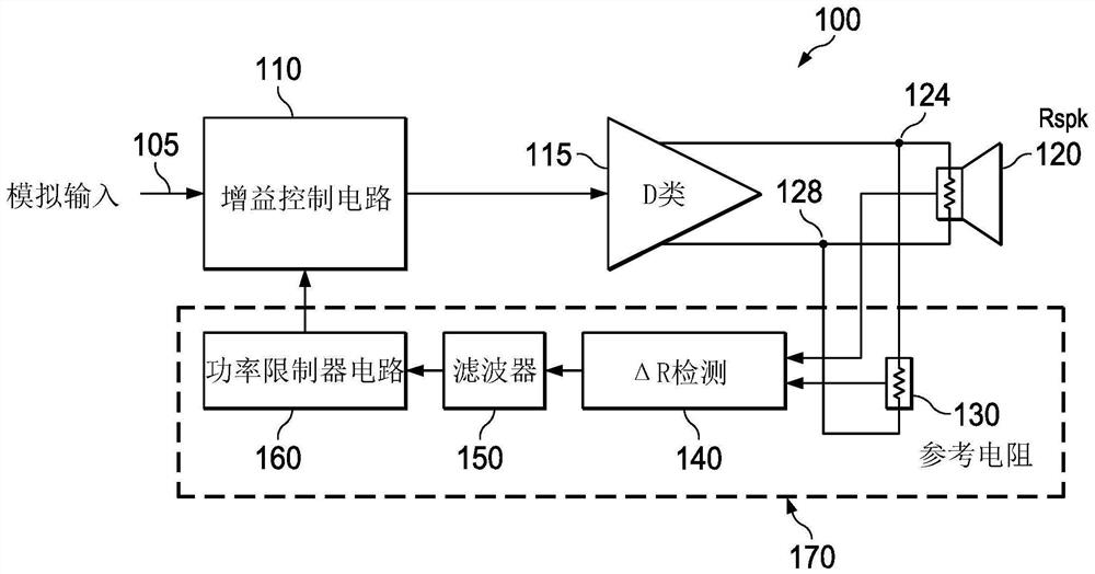
[0014] The disclosed thermal protection circuits for audio amplifier systems are analog circuits and occupy less area on a semiconductor die than thermal protection circuits that rely on digital signal processing and associated ADCs. The example thermal protection circuit also determines the temperature of the connected speakers and allows the audio amplifier system to achieve less conservative audio output signal thresholds and increased maximum allowable power compared to audio amplifier systems that rely on feed-forward thermal protection.

[0015] An example thermal protection circuit compares the output load current to a known reference current. The reference current is calibrated to match the resistance of the loudspeaker at a known temperature, which is referred to herein as the resistance of the loudspeaker at time t0 under resting conditions, and can be determined at the time of manufacture. The difference between the two currents is caused by an increase in the tempe...


PUM


Abstract

A circuit (200) comprises a sensing resistor (Rs) with a resistance Rs, a first amplifier circuit (210) with a first gain factor G, a second amplifier circuit (245) with a second gain factor (l / A), a third amplifier circuit, a current mirror (255), a buffer (275), and a peak voltage detector. The first amplifier circuit is coupled to the sensing resistor at a first node (205) and a second node (124) and to the second amplifier circuit, which is further coupled to the current mirror. The buffer is coupled to the current mirror and to the third amplifier circuit, which is further coupled to the peak voltage detector and configured to receive a voltage across a load and a voltage on a ground node. In some implementations, the load is a speaker (120). In some implementations, a filter (150) is coupled between the first and the second amplifier circuits.

Description

Background technique [0001] Speakers are often overdriven to obtain the desired loudness of the audio output signal. However, overdriving a speaker can cause the speaker to overheat and cause permanent damage to the speaker. Overheating of the speaker can cause changes in the shape of the speaker diaphragm, distorting the audio signal output from the speaker. An overheated speaker can also melt components inside the speaker, including the glue that holds the voice coil to the speaker driver, the solder that connects the amplifier to the speaker, and the insulation on the voice coil. Melting the insulation on the voice coil causes the voice coil to short out and limit the loudness of the speaker, reducing the resistance of the speaker and further increasing the temperature of the speaker. [0002] These mechanical failures within the speaker due to increased temperature can cause the speaker to fail. To reduce the chance of these mechanical failures, the power applied to the...

Claims


Application Information

Patent Timeline
Patent Type & Authority Applications(China)
IPC IPC(8): G01R19/04H03G3/20H03F3/181
CPCH04R2430/01H04R3/007H03F3/2171H03F1/52H03F3/45475H03F2200/03H03F2203/45151H03F2203/45528H03F2200/435H03F3/187H03G3/3005H03G3/005H03F3/45H03F3/217
Inventor J·S·查达
Owner TEXAS INSTR INC
Why Eureka
Try Eureka