Novel rice hulling part of rice huller
A grain hulling machine and a new type of technology are applied in grain finishing, grain hulling, grain processing and other directions, and can solve the problems of simple structure, inconvenient adjustment of the belt tension of the grain husking machine, and inconvenient adjustment of the rotational speed of each roller shaft of the grain hulling machine. , to achieve the effect of simple structure, convenient adjustment of rubber roller speed change and convenient control
- Summary
- Abstract
- Description
- Claims
- Application Information
AI Technical Summary
Problems solved by technology
Method used
Image
Examples
Embodiment 1
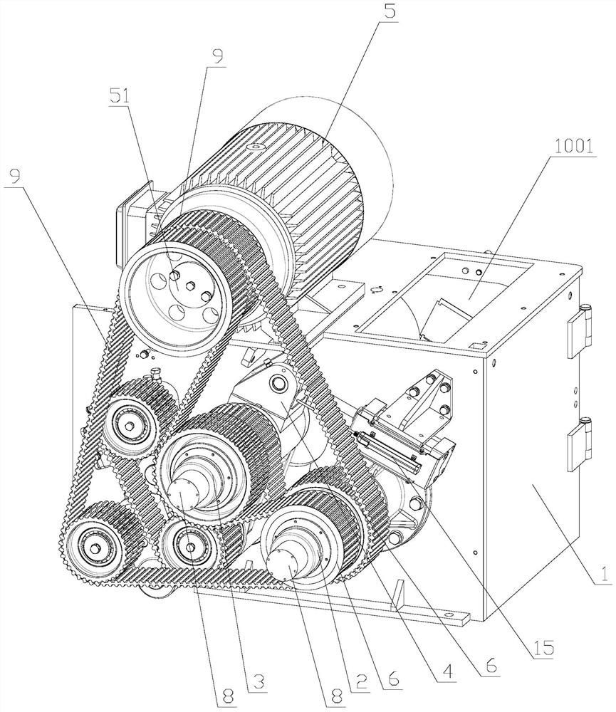
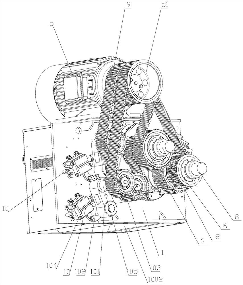
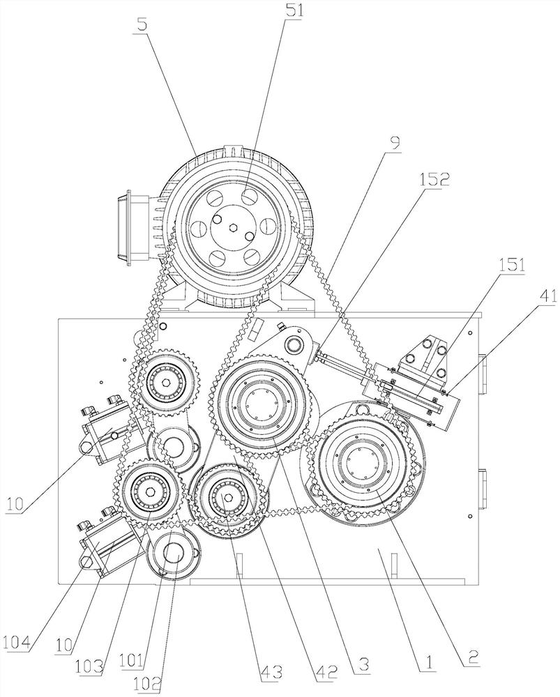
[0029] refer to Figure 1-9, the hulling part of a novel hulling machine of the present invention includes a body 1, a hulling chamber is provided in the body 1, and a feed port 1001 and an outlet connected to the hulling chamber are provided on the body 1. Material port 1002, at least one fixed rubber roller 2 is fixed in the body 1, and at least one movable rubber roller 3 that can cooperate with it is arranged beside the fixed rubber roller 2, and the end of the movable rubber roller 3 is provided for adjusting the The rubber roller adjustment mechanism 4 of the movable rubber roller 3 relative to the position of the fixed rubber roller 2, the body 1 is provided with a drive motor 5, and the rotation shaft of the drive motor 5 is provided with a main drive pulley 51. Two belts 9 are arranged on the driving pulley 51, and two rubber roller pulleys 6 with different transmission ratios are arranged on the fixed rubber roller 2 and the movable rubber roller 3, and the rubber ro...
Embodiment 2
[0035] refer to Figure 7 , Figure 8 and Figure 9 , on the basis of Embodiment 1, the fixed rubber roller 2 has the same structure as the movable rubber roller 3, and both include a rubber roller shaft 12 and a rubber roller body 11 sleeved on the rubber roller shaft 12. The two ends of the rubber roller shaft 12 are respectively provided with a main supporting seat 13 and a secondary supporting seat 14 which can cooperate with the rubber roller shaft 12 .
[0036] refer to Figure 7 , Figure 8 and Figure 9 The two ends of the rubber roller body 11 are respectively provided with a main support end 111 for detachable connection with the main support base 13 and an auxiliary support end 112 that can interfere with the auxiliary support base 14. The main support end 111 is provided with a main support end inner hole 1111, and the auxiliary support end 112 is provided with an auxiliary support end inner hole 1121, and the diameter of the auxiliary support end inner hole 1...
Embodiment 3
[0039] refer to figure 1 , figure 2 , image 3 The rubber roller adjustment mechanism 4 is provided with a device for measuring the adjustment amount of the rubber roller adjustment mechanism 4 so as to calculate the distance between the first rubber roller 2 and the second rubber roller 3 so as to convert the diameter of the rubber roller Distance measuring mechanism 15. The distance between the first rubber roller 2 and the second rubber roller 3 is calculated by setting the distance measurement mechanism 15 to measure the adjustment amount of the rubber roller adjustment mechanism 4, so as to convert the diameter of the one-sided rubber roller. The measurement is more convenient, the data is more accurate, and it is convenient. To know the remaining condition of the rubber roller, it is easy to understand the real-time wear degree.
[0040] refer to figure 1 , figure 2 , image 3 , the distance measuring mechanism 15 includes an electronic ruler 151 and an induction...
PUM
 Abstract
Description
Claims
Application Information
 - R&D
- Intellectual Property
- Life Sciences
- Materials
- Tech Scout
- Unparalleled Data Quality
- Higher Quality Content
- 60% Fewer Hallucinations
Browse by: Latest US Patents, China's latest patents, Technical Efficacy Thesaurus, Application Domain, Technology Topic, Popular Technical Reports.
© 2025 PatSnap. All rights reserved.Legal|Privacy policy|Modern Slavery Act Transparency Statement|Sitemap|About US| Contact US: help@patsnap.com


