Baby carrier speed change drive circuit
A variable-speed drive and circuit technology, applied in the control drive, electric vehicles, vehicle components, etc., can solve the problems of high-speed FETs with large load, high cost, and easy damage.
- Summary
- Abstract
- Description
- Claims
- Application Information
AI Technical Summary
Problems solved by technology
Method used
Image
Examples
Embodiment Construction
[0010] The present invention will be described in detail below in conjunction with the accompanying drawings and specific embodiments.
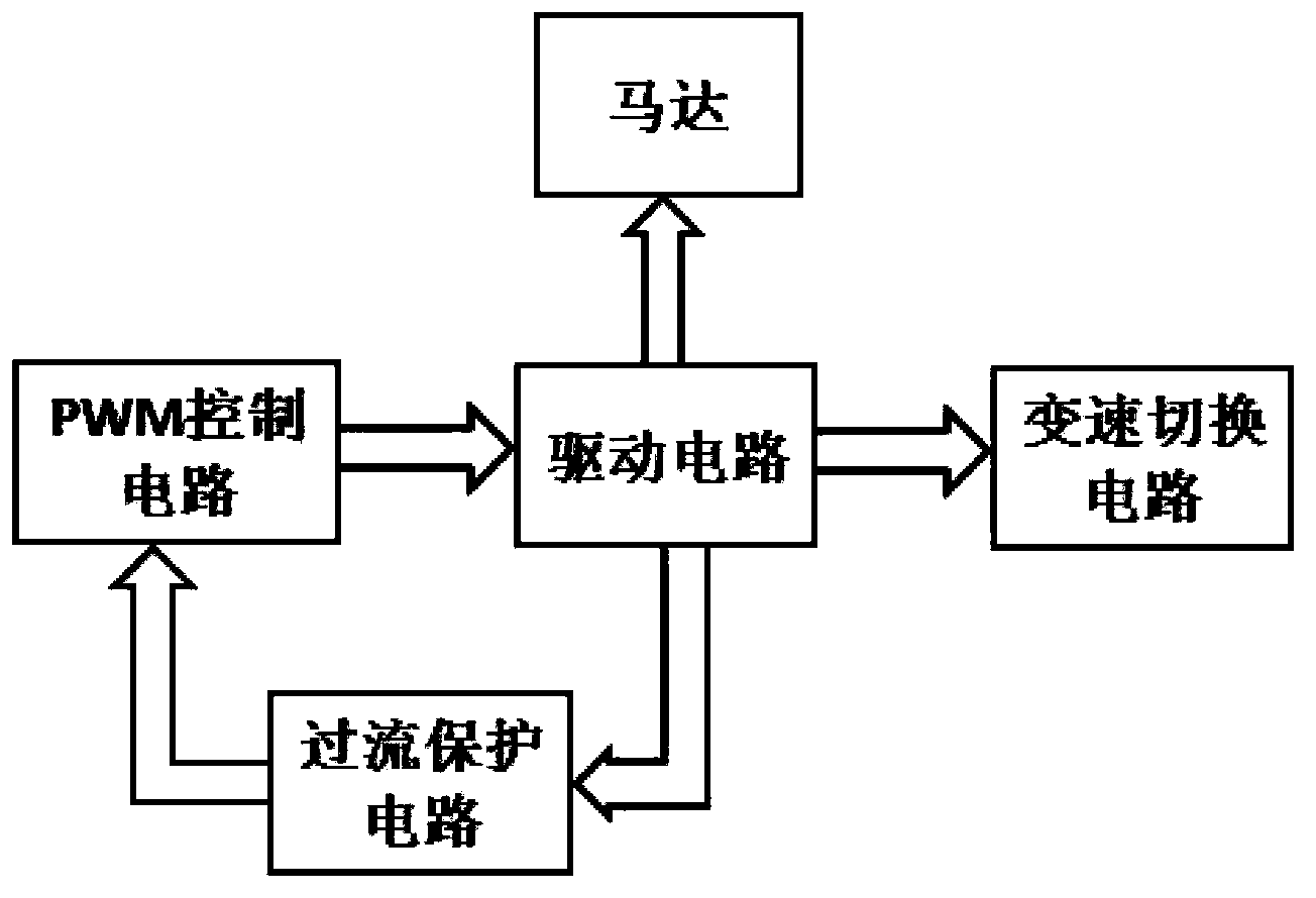
[0011] Such as figure 1 As shown, the PWM control circuit outputs a pulse square wave with a certain duty ratio to the drive circuit, and the drive circuit drives the motor to work and limits the current flowing through the motor, so as to achieve the purpose of variable speed. The variable speed switching module enables the car to switch between high and low speeds. The overcurrent protection module cuts off the driving pulse when the motor is stuck to prevent the motor and FET from burning out.
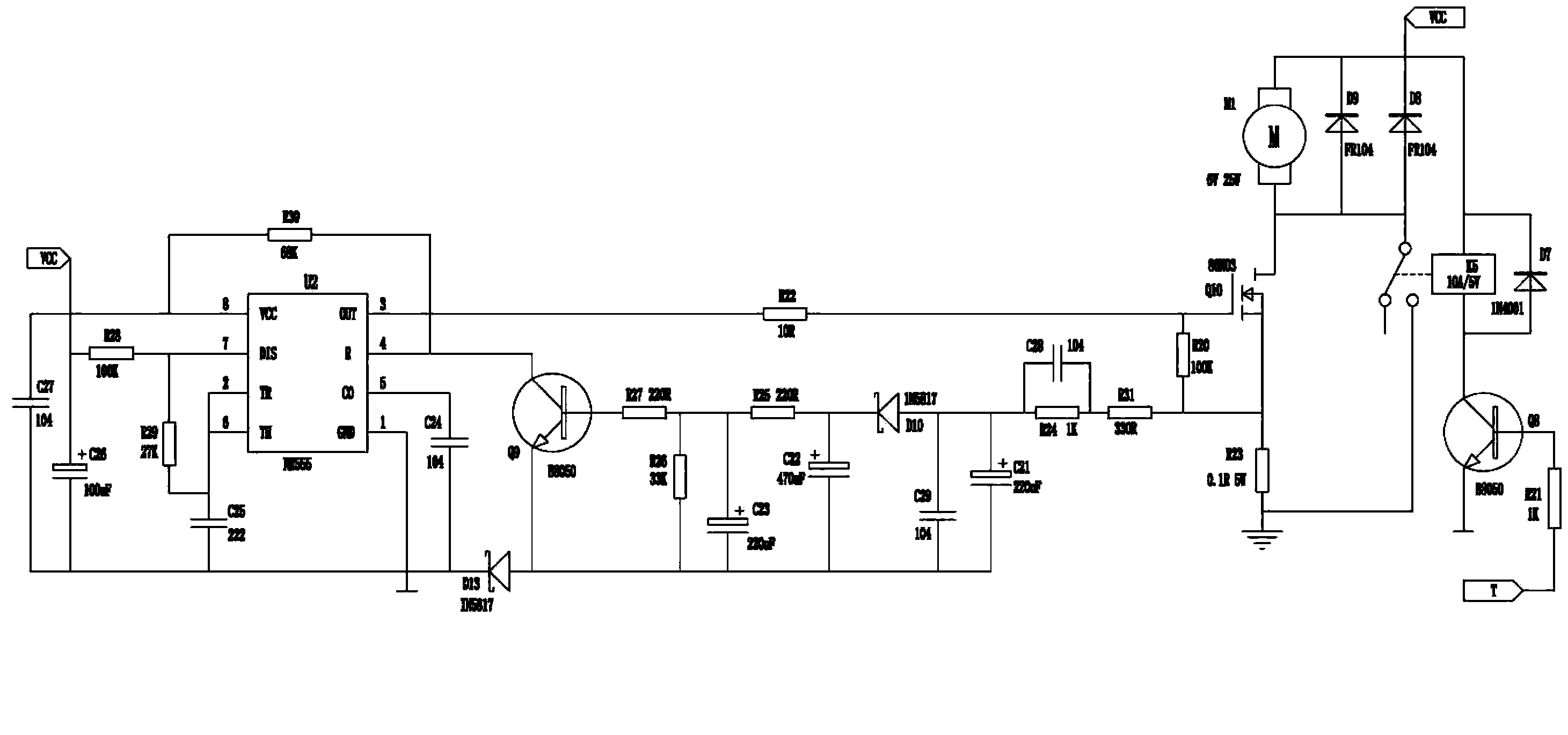
[0012] refer to figure 2 It can be seen that when VCC has a voltage input, the third pin of the time base IC U2 (NE555) outputs a pulse square wave with a duty ratio of 82.5% to the gate of the field effect transistor Q10, and the drain of the field effect transistor works , and then drive the motor M1 to work. Because the field effect transist...
PUM
 Abstract
Description
Claims
Application Information
 - R&D
- Intellectual Property
- Life Sciences
- Materials
- Tech Scout
- Unparalleled Data Quality
- Higher Quality Content
- 60% Fewer Hallucinations
Browse by: Latest US Patents, China's latest patents, Technical Efficacy Thesaurus, Application Domain, Technology Topic, Popular Technical Reports.
© 2025 PatSnap. All rights reserved.Legal|Privacy policy|Modern Slavery Act Transparency Statement|Sitemap|About US| Contact US: help@patsnap.com


