
Energy-saving annealing furnace for carbon steel forging heat treatment and operation method thereof

A technology for forging heat treatment and annealing furnaces, applied in heat treatment furnaces, heat treatment equipment, furnaces, etc., to achieve the effects of increasing annealing efficiency, improving heat exchange time, and avoiding incomplete annealing

Active Publication Date: 2021-11-02
沂水金星金属制品有限公司
View PDF6 Cites 1 Cited by
  • Summary
  • Abstract
  • Description
  • Claims
  • Application Information

AI Technical Summary

Problems solved by technology

[0004] Aiming at the deficiencies in the use of existing annealing furnaces proposed in the background technology, the present invention provides an energy-saving annealing furnace for carbon steel forging heat treatment and its The operation method has the advantages of uniform heating of the annealed material in the annealing furnace, long heat exchange time between the hot air and the material, and multi-material annealing can be performed in one operation, and solves the technical problems raised in the above-mentioned background technology

Method used


Image

  • Energy-saving annealing furnace for carbon steel forging heat treatment and operation method thereof
  • Energy-saving annealing furnace for carbon steel forging heat treatment and operation method thereof
  • Energy-saving annealing furnace for carbon steel forging heat treatment and operation method thereof

Examples


Embodiment Construction

[0025] The following will clearly and completely describe the technical solutions in the embodiments of the present invention with reference to the accompanying drawings in the embodiments of the present invention. Obviously, the described embodiments are only some, not all, embodiments of the present invention. Based on the embodiments of the present invention, all other embodiments obtained by persons of ordinary skill in the art without making creative efforts belong to the protection scope of the present invention.

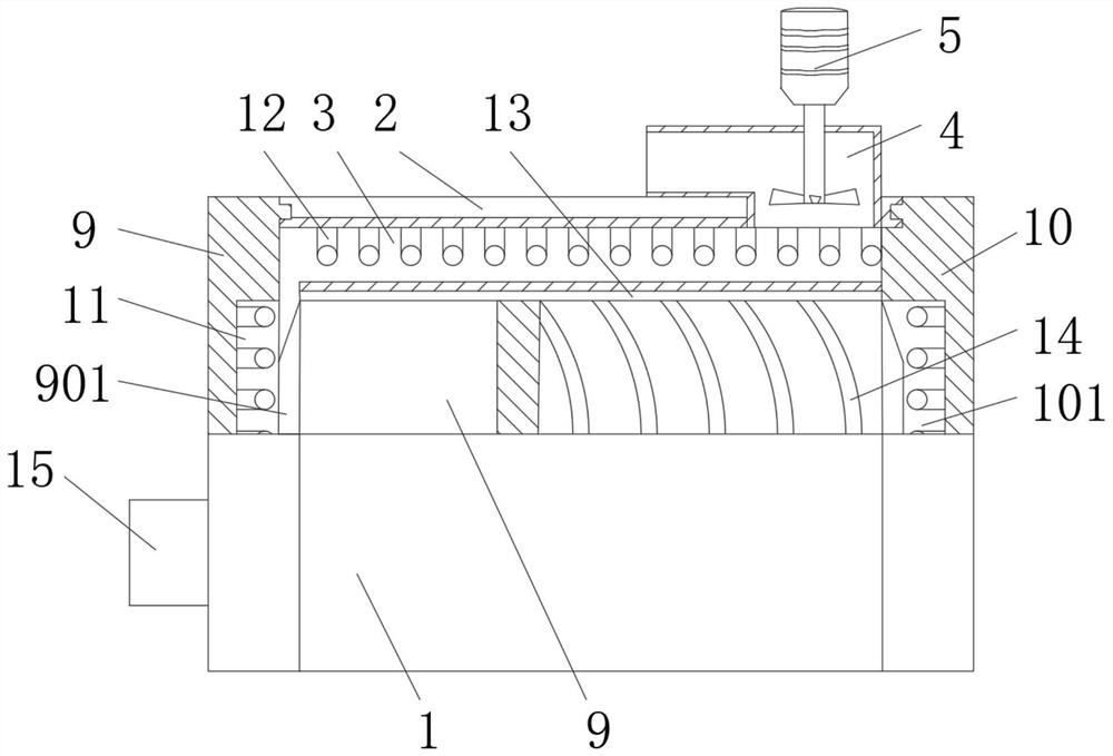
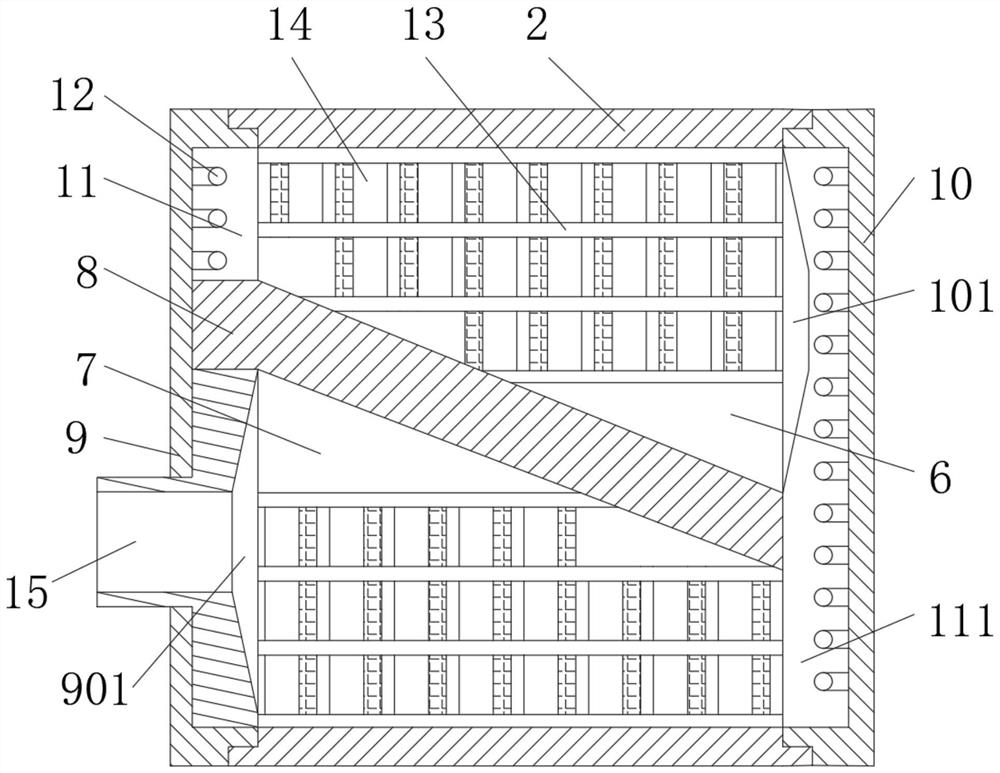
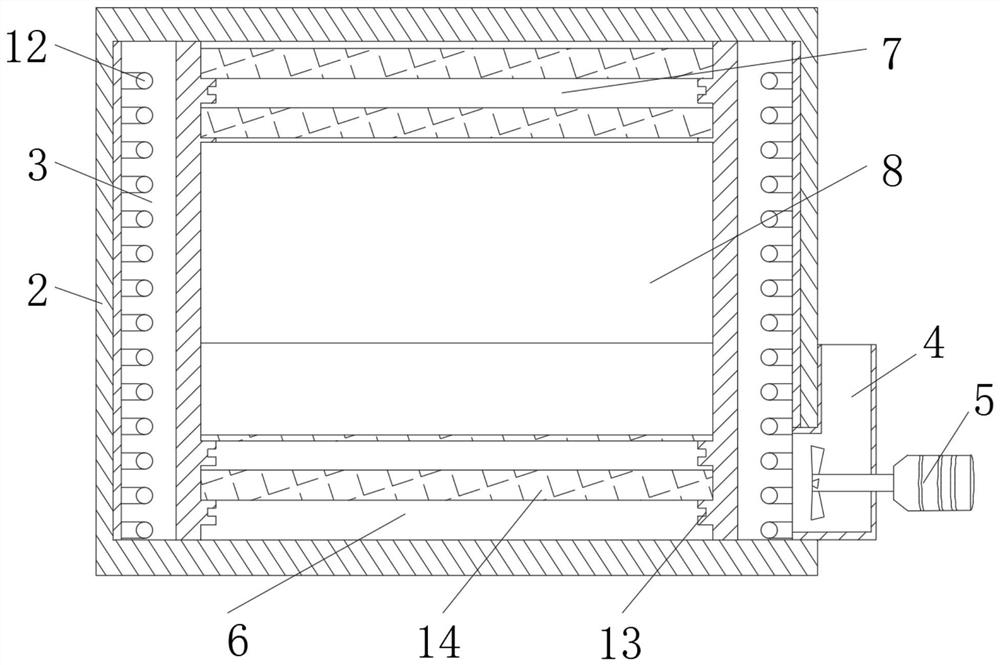
[0026] see Figure 1-4 , an energy-saving annealing furnace for carbon steel forging heat treatment, comprising an annealing furnace body 1, the annealing furnace body 1 is divided into an insulating layer 2, a heating layer 3 and an inner cavity from the outside to the inside, and one side of the annealing furnace body 1 An air inlet pipe 4 that runs through the insulation layer 2 to the heating layer 3 is fixedly connected, and a circulating fan 5 is fixedly...


PUM


Abstract

The invention relates to the technical field of carbon steel heat treatment, and discloses an energy-saving annealing furnace for carbon steel forging heat treatment and an operation method thereof. The energy-saving annealing furnace comprises an annealing furnace body, wherein the annealing furnace body is divided into a heat preservation layer, a heating layer and an inner cavity from outside to inside, one side of the annealing furnace body is fixedly connected with an air inlet pipe penetrating through the heat preservation layer to the heating layer, a circulating fan is fixedly connected into the air inlet pipe, the inner cavity is divided into a first inner cavity and a second inner cavity, an inclined partition layer is installed between the first inner cavity and the second inner cavity, and clamping grooves which are evenly distributed are formed in the first inner cavity and the second inner cavity. By designing the inclined partition layer, two annealing inner cavities with right-trapezoid-shaped cross sections are formed in the annealing furnace, so that hot air is always introduced into the inner cavities from a smaller inlet, and the hot air is automatically and uniformly diffused by gradually increasing the space of the inner cavities, and meanwhile, the air speed is reduced, the heat exchange time of the hot air to materials is prolonged, and the annealing efficiency is improved.

Description

technical field [0001] The invention relates to the technical field of carbon steel heat treatment, in particular to an energy-saving annealing furnace for carbon steel forging heat treatment and an operation method thereof. Background technique [0002] The annealing furnace is a common heat treatment equipment. It mainly heats the air and uses a circulating fan to uniformly heat the material to be processed in the furnace to achieve the purpose of material annealing. [0003] However, the existing annealing furnace for forging heat treatment of carbon steel uses a circulating fan to make the heat in the inner cavity uniform, and the effect is not good due to the shape of the annealed material. The temperature of the parts is often low, which leads to local gaps in the annealing effect caused by uneven heating of carbon steel, making the crystals produced locally in carbon steel substandard, and the utensils containing carbon steel are in contact with the bottom surface of ...

Claims


Application Information

Patent Timeline
Patent Type & Authority Applications(China)
IPC IPC(8): C21D1/26C21D9/00
CPCC21D1/26C21D9/0006C21D9/0025
Inventor 许国平
Owner 沂水金星金属制品有限公司
Learn More