
Ceramic-based flame tube positioning structure

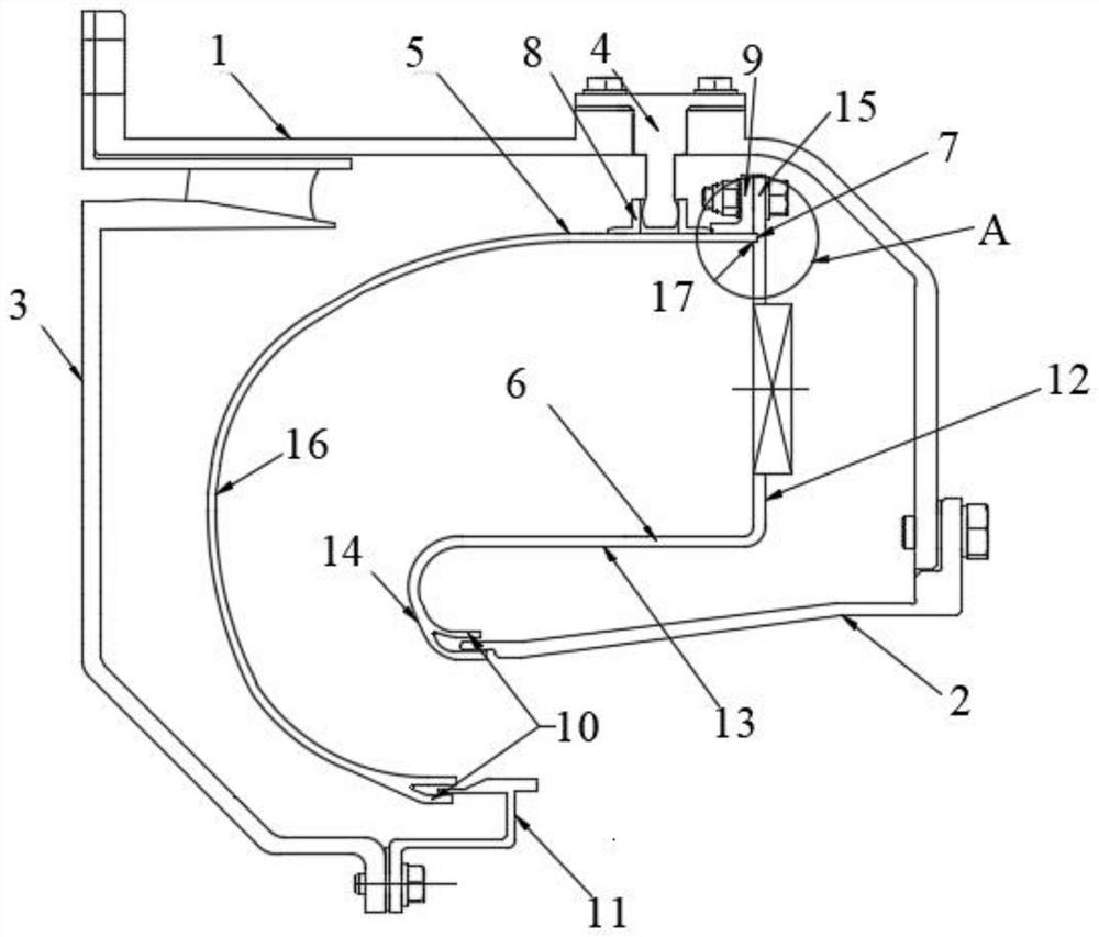
A positioning structure and flame tube technology, applied in the field of aero-engines, can solve the problems such as the failure to improve the temperature resistance of the flame tube head, the inability to solve the positioning and connection of the flame tube, and the difficulty in ensuring the relative position relationship of the flame tube. The effect of reducing the amount of cooling gas and improving the temperature resistance

Active Publication Date: 2021-11-02
AECC HUNAN AVIATION POWERPLANT RES INST
View PDF7 Cites 3 Cited by
  • Summary
  • Abstract
  • Description
  • Claims
  • Application Information

AI Technical Summary

Problems solved by technology

Although the fixed structure of the flame tube has basically realized the application and connection of the ceramic matrix composite material on the flame tube of the combustion chamber, the head of the flame tube is still made of metal material, and the temperature resistance of the head of the flame tube has not been improved, and it cannot solve the problem. Positioning and Connection of Flame Tubes Made of All-Ceramic Matrix Composites
[0005] The use of metal materials for the head of the flame tube limits the improvement of the temperature resistance of the head wall. The existing structural scheme cannot realize the positioning and connection of the all-ceramic matrix composite material flame tube; Positional relationship

Method used


Image

  • Ceramic-based flame tube positioning structure
  • Ceramic-based flame tube positioning structure

Examples


Embodiment Construction

[0024] In order to make the object, technical solution and advantages of the present invention clearer, the technical solution of the present invention will be further described in detail through the following embodiments and in conjunction with the accompanying drawings. In the specification, the same or similar reference numerals designate the same or similar components. The following description of the embodiments of the present invention with reference to the accompanying drawings is intended to explain the general inventive concept of the present invention, but should not be construed as a limitation of the present invention.

[0025] In addition, in the following detailed description, for purposes of explanation, numerous specific details are set forth in order to provide a comprehensive understanding of the embodiments of the present disclosure. It may be evident, however, that one or more embodiments may be practiced without these specific details. In other instances,...


PUM


Abstract

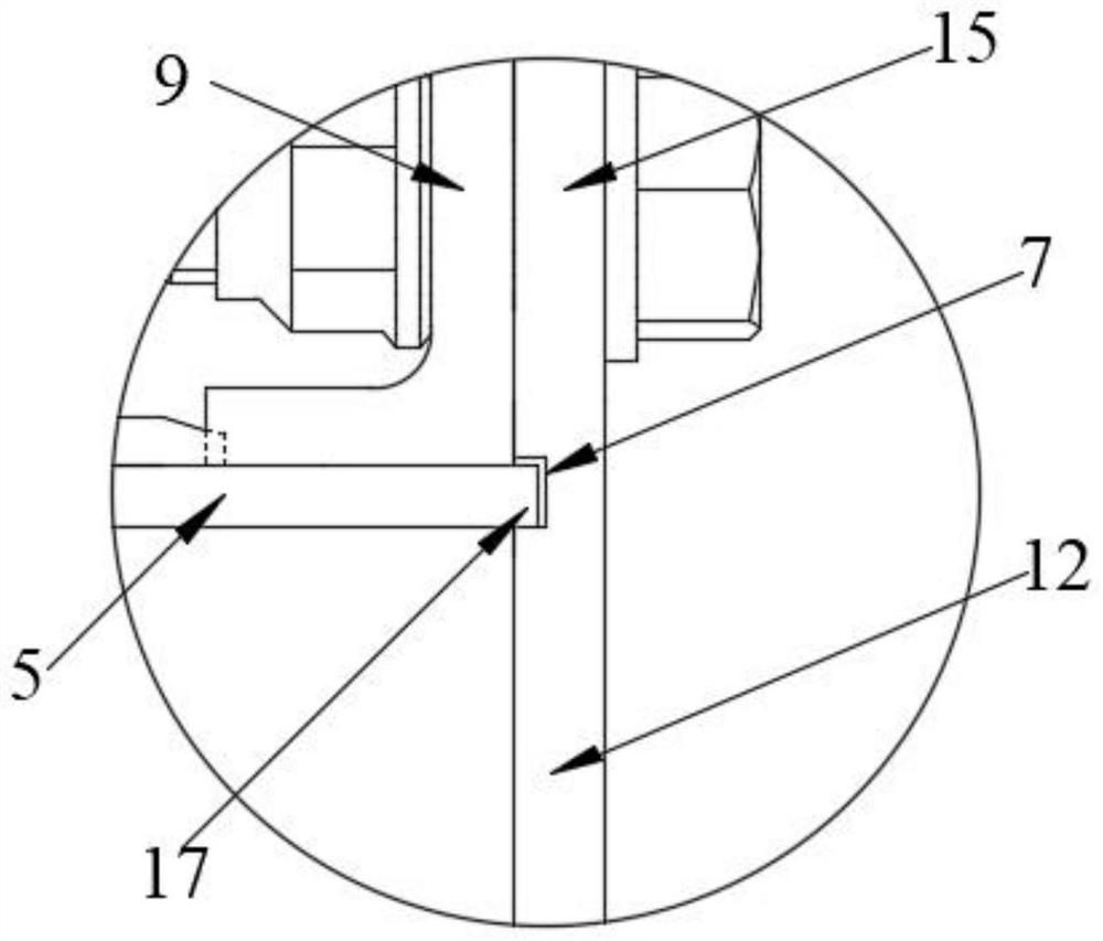
The invention discloses a ceramic-based flame tube positioning structure, and belongs to the technical field of aero-engines; the ceramic-based flame tube positioning structure comprises a flame tube head integrally formed with an inner ring of a flame tube; the flame tube head comprises a flange arranged on the outer edge of the flame tube head and a concave spigot close to the flange; the inner ring of the flame tube comprises a small bent pipe; an annular groove is formed in the tail end of the small bent pipe; the inner ring of the flame tube is in lap joint with a combustion chamber inner case through the annular groove; a plurality of positioning pins are circumferentially and uniformly distributed on a combustion chamber outer case; a plurality of positioning pin seats matched with the positioning pins are uniformly distributed on the ring surface of an outer ring of the flame tube and are used for supporting the flame tube. In the working state, through the reserved gap between the positioning pin and the hole bottom of the positioning pin seat and the gap of the annular groove, the space requirement needed by thermal expansion of the positioning pin, the combustion chamber inner case and an outlet supporting ring can be met. No matter in a cold state or a hot state, the combustion chamber inner case and the outlet supporting ring can also play a role in auxiliary support on the wall surface of the flame tube.

Description

technical field [0001] The invention belongs to the technical field of aero-engines, and in particular relates to a ceramic-based flame tube positioning structure. Background technique [0002] With the development of engine technology, the working temperature of the flame tube in the combustion chamber is gradually increasing. On the basis of meeting the requirements of light weight, high reliability and long life, the material of the flame tube is required to further improve the temperature resistance of the material. Using ceramic matrix composites to replace traditional superalloys is the best way to improve the temperature resistance of engine combustion chamber components and engine efficiency. [0003] Ceramic matrix composites are a type of composite materials that are composited with ceramics and various fibers. Ceramic matrix composites have excellent properties such as high temperature resistance, high strength, high stiffness, relatively light weight, and corrosi...

Claims


Application Information

Patent Timeline
IPC IPC(8): F23R3/42F23R3/60
CPCF23R3/42F23R3/60Y02T10/12
Inventor 戴金鑫郎旭东陈智莹刘丽娟张荣幸杨大伟
Owner AECC HUNAN AVIATION POWERPLANT RES INST
Learn More