A duct fin evaporator

A finned evaporator and finned technology, applied in the field of pipe finned evaporators, can solve the problems of poor air flow, affecting the heat dissipation efficiency of fins, excessive heat accumulation of fins, etc., to improve the cleaning effect, The effect of prolonging the contact time and prolonging the contact area

Active Publication Date: 2022-07-22
合肥美菱有色金属制品有限公司
View PDF7 Cites 1 Cited by
  • Summary
  • Abstract
  • Description
  • Claims
  • Application Information

AI Technical Summary

Problems solved by technology

[0004] However, there are still major defects in the prior art, such as: 1. The fins will accumulate dust during long-term use. If they are not cleaned in time, the accumulation of dust on the fins will affect the heat dissipation efficiency of the fins, and will cause the fins to accumulate too much. More heat reduces its service life; 2. The above technology enhances air circulation by slotting on the outside of the fins, but the air blown on the inside of the fins still cannot flow well, and the air blown on the outside of the fins directly passes through The slots flow out, and there is no sufficient heat exchange with the surface of the fins, so the improvement of the heat dissipation performance of the fins is small

Method used


Image

  • A duct fin evaporator
  • A duct fin evaporator
  • A duct fin evaporator

Examples


Embodiment Construction

[0029] The technical solutions in the embodiments of the present invention will be clearly and completely described below with reference to the accompanying drawings in the embodiments of the present invention. Obviously, the described embodiments are only a part of the embodiments of the present invention, but not all of the embodiments. Based on the embodiments of the present invention, all other embodiments obtained by those of ordinary skill in the art without creative efforts shall fall within the protection scope of the present invention.

[0030] see Figure 1-7 , the present invention provides a kind of technical scheme:

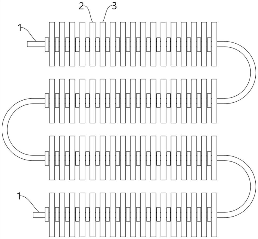
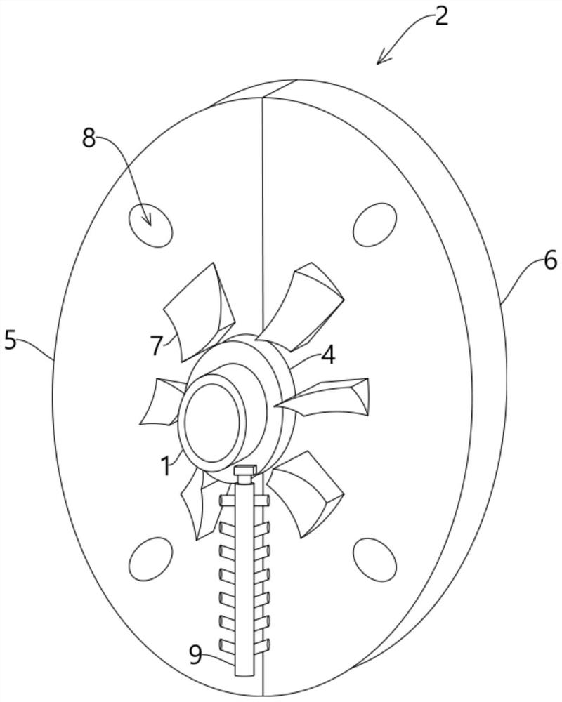
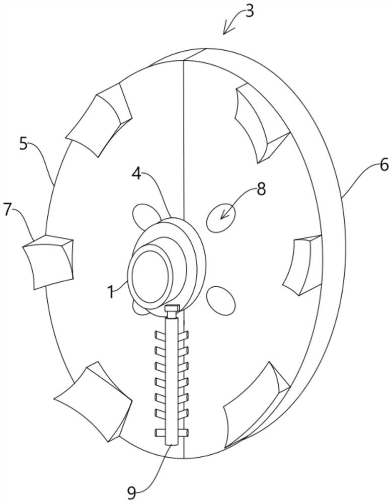
[0031] A pipe-finned evaporator, comprising an evaporation tube 1, a plurality of first fins 2 and second fins 3 are arranged on the evaporation tube 1 in a cross-moving sleeve, and the first fins 2 and the second fins 3 are used to accelerate heat dissipation. , the effect of improving the heat exchange efficiency of the evaporation tube 1, and the...


PUM


Abstract

The invention discloses a pipe-finned evaporator, wherein a plurality of first fins and second fins are crossed and sleeved on the evaporation tube, and the thickness of the air-inducing blocks of the first fins and the second fins is along the The gradual trend of the circumferential direction of the annular distribution is opposite, and the thickness of any air-inducing block of the first fin and the second fin is opposite to the gradual trend in the direction away from the center of the circle, and an elastic cleaning brush is fixedly connected to the outside of the elastic cleaning cylinder, so The elastic cleaning cylinder is fixedly connected with an elastic extrusion column that cooperates with the air-inducing block, and the water storage tank is slidably provided with a second magnetic block that magnetically cooperates with the first magnetic block to press water. The rotation of the first fin and the second fin disturbs the fluid state of the air, and through the cooperation of the ventilation hole and the air-inducing block, the contact area and duration of the air and the fin are increased while guiding the air circulation, and the elastic cleaning is also carried out. The matching arrangement of brushes and elastic extrusion columns, etc., cleans the surface of the fins.

Description

technical field [0001] The invention relates to the technical field of evaporators, in particular to a pipe fin evaporator. Background technique [0002] The evaporator is a very important part of the four major components of refrigeration. The low-temperature condensed liquid passes through the evaporator to exchange heat with the outside air, and absorbs heat through vaporization to achieve the effect of refrigeration. At present, fins are generally installed on the finned evaporator for heat dissipation. However, due to the high heat exchange temperature, the air between the fins is not easy to circulate, which makes the heat dissipation effect of the evaporator poor, which often leads to the accumulation of excessive heat on the fins and shortens the fins. service life. [0003] In the prior art, the application number is "201820683471.0" of an aluminum tube and aluminum fin evaporator. The fins are sleeved on the outside of the evaporation tube. By selecting circular f...

Claims


Application Information

Patent Timeline
Patent Type & Authority Patents(China)
IPC IPC(8): F25B39/02F28F1/20
CPCF25B39/02F28F1/20F25B2339/02
Inventor 王庆友王耀王佩璇黄凯奇
Owner 合肥美菱有色金属制品有限公司
Why Eureka
Try Eureka