Quick exchange type balloon stent mounting device and stent mounting method

An installation device and exchange-type technology, applied in the direction of brackets, etc., can solve the problems of easy complications and increased operation time, and achieve the effect of reducing operation steps, improving operation success rate, reducing the number of instrument exchange and operation time

Pending Publication Date: 2021-11-05
SUZHOU ZENITH VASCULAR SCITECH LTD
View PDF0 Cites 2 Cited by
  • Summary
  • Abstract
  • Description
  • Claims
  • Application Information

AI Technical Summary

Problems solved by technology

In the above process, the microcatheter and the balloon catheter need to be alternately inserted into the blood vessel multiple times, which is likely to cause complications and increase the operation time

Method used


Image

  • Quick exchange type balloon stent mounting device and stent mounting method
  • Quick exchange type balloon stent mounting device and stent mounting method
  • Quick exchange type balloon stent mounting device and stent mounting method

Examples


Embodiment 1

[0048] In the current operation process, the doctor needs to deliver the microcatheter and microguide wire to the lesion, then remove the microcatheter, insert the balloon catheter to pre-dilate the lesion, and then withdraw the balloon catheter. Through the microcatheter, the stent is delivered to the lesion site through the microcatheter, released and automatically expanded to expand the blood vessel. In the above process, the microcatheter and the balloon catheter need to be alternately inserted into the blood vessel multiple times, which is likely to cause complications and increase the operation time.

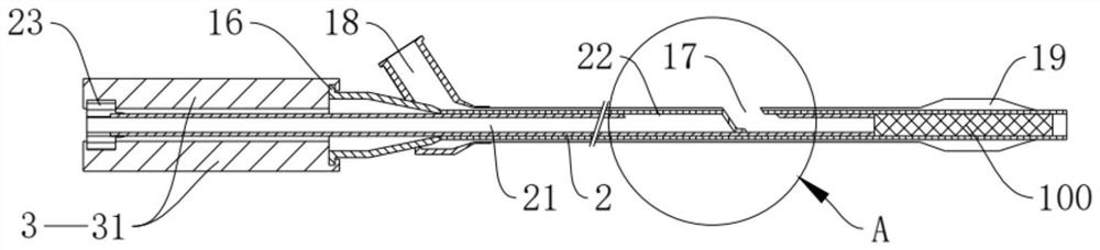
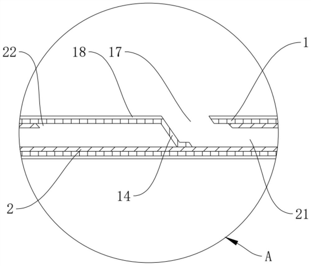
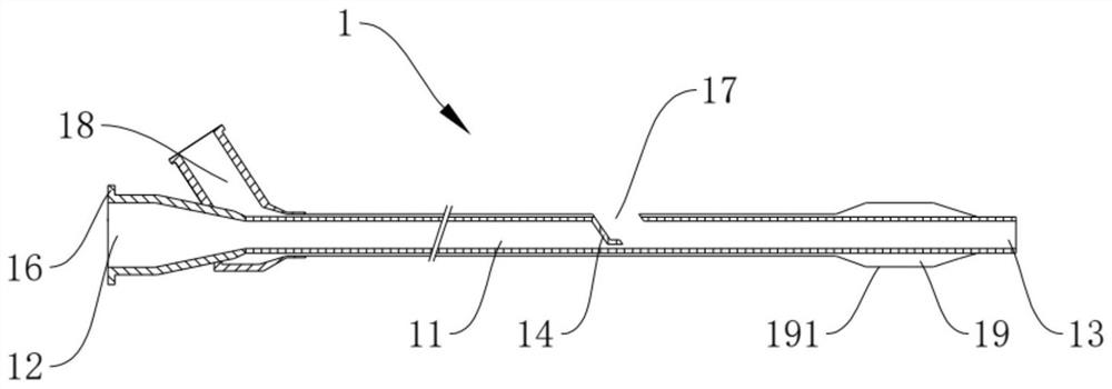
[0049] To solve the above problems, such as Figure 1-Figure 5 As shown, this embodiment provides a rapid exchange balloon stent installation device, which includes a balloon dilation catheter 1 , a micro guide wire (not shown in the figure) and a stent release tube 2 . It should be noted that the “proximal end” in this embodiment refers to the end close to the operator, ...

Embodiment 2

[0068] This embodiment also provides a quick-exchange balloon stent installation device. The difference between this embodiment and Embodiment 1 is that the installation method of the stent release tube 2 is different from Embodiment 1, such as Figure 6-Figure 8 As shown, in this embodiment, the stent release tube 2 is passed through the first through hole 11 of the balloon dilatation catheter 1 through the threading hole 17, and the stopper component 3 in the first embodiment is omitted. In this embodiment, the first guide wall 14 of the balloon dilation catheter 1 in Embodiment 1 is replaced with a second guide wall 15, the second guide wall 15 is arranged obliquely, and part of the side wall of the second guide wall 15 is fixed to the first guide wall 15. On the side wall of the through hole 11, the side wall of the second guide wall 15 near the side of the thread hole 17 is fixed on the thread hole 17, and the end of the second guide wall 15 away from the thread hole 17 fa...


PUM


Abstract

The invention relates to the technical field of intravascular self-expanding stent conveying and discloses a quick exchange type balloon stent mounting device and a stent mounting method. The quick exchange type balloon stent mounting device is used for mounting a self-expanding stent at a diseased region of a blood vessel and comprises a balloon dilatation catheter, a micro guide wire and a stent release tube, a first through hole is formed in the balloon dilatation catheter along a length direction, and a wire penetrating hole is formed in the side wall of the first through hole; the micro guide wire can enter the first through hole through a far end of the balloon dilatation catheter and penetrate out of the wire penetrating hole; an expansion part is arranged at the far end of the balloon dilatation catheter, and a self-expanding stent is slidably mounted in the first through hole and located at the far end of the balloon dilatation catheter; and the stent release tube is arranged in the first through hole of the balloon dilatation catheter in a sliding mode, and a far end of the stent release tube is abutted against the self-expanding stent. The self-expanding stent can be conveyed and mounted by mounting the balloon dilatation catheter at a time, and the success rate of an operation is increased.

Description

technical field [0001] The invention relates to the technical field of intravascular self-expandable stent delivery, in particular to a fast-exchange balloon stent installation device and a stent installation method. Background technique [0002] Vascular stenosis is a common vascular disease and an important cause and risk factor of ischemic vascular disease. At present, vascular stent implantation is one of the important technologies for the treatment of vascular stenosis. The stent implantation of the self-expandable stent is usually pre-expanded with a balloon catheter, and then the stent is delivered to the lesion site to be released and automatically expanded to expand the blood vessel. [0003] In the current operation process, the doctor needs to deliver the microcatheter and microguide wire to the lesion, then remove the microcatheter, insert the balloon catheter to pre-dilate the lesion, and then withdraw the balloon catheter. Through the microcatheter, the stent...

Claims


Application Information

Patent Timeline
Patent Type & Authority Applications(China)
IPC IPC(8): A61F2/958
CPCA61F2/958
Inventor 李光轩郭力友夏洁
Owner SUZHOU ZENITH VASCULAR SCITECH LTD
Why Eureka
Try Eureka