
Metal straight bar round hole punching equipment

A straight bar and round hole technology, applied in the field of metal straight bar round hole punching equipment, can solve the problems of increased workload, falling on the ground, dirty ground, etc., to reduce labor intensity, improve work efficiency, and facilitate processing effect

Active Publication Date: 2021-11-05
朝阳市多元合金铸造有限责任公司
View PDF10 Cites 0 Cited by
  • Summary
  • Abstract
  • Description
  • Claims
  • Application Information

AI Technical Summary

Problems solved by technology

[0005] In order to overcome the shortcomings of most metal straight punching machines, the punching effect is not good, and the metal straight scraps fall directly on the ground after punching, causing the ground to be dirty and increasing people's workload. Technical problems to be solved : To provide a metal straight bar punching equipment that has the function of collecting waste materials and does not need to manually push materials

Method used


Image

  • Metal straight bar round hole punching equipment
  • Metal straight bar round hole punching equipment
  • Metal straight bar round hole punching equipment

Examples


Embodiment 1

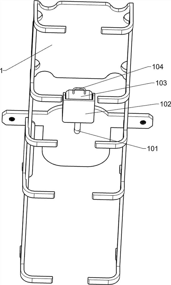
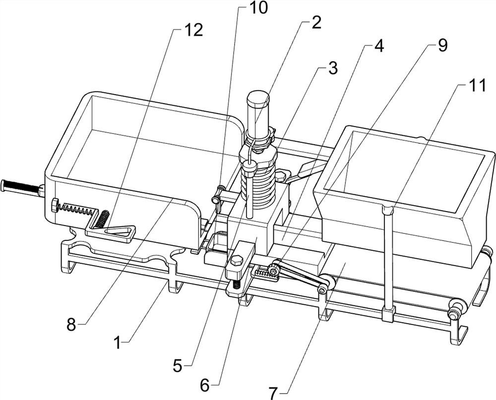
[0028] A metal straight bar punching round hole equipment, such as figure 1 and figure 2 As shown, it includes a base 1, a cylinder 2, an extruding column 3, a supporting platform 4, a pressing mechanism 5 and a fixing mechanism 6, the top of the base 1 is provided with a supporting platform 4, the top of the supporting platform 4 is provided with a fixing mechanism 6, and the fixing mechanism The top of 6 is provided with a pressing mechanism 5, the top of the pressing mechanism 5 is provided with a cylinder 2, and the bottom of the pressing mechanism 5 is provided with an extruding column 3, and the extruding column 3 is slidably connected with the fixing mechanism 6.

[0029] When people need to make round holes on the metal straight bar, people place the metal straight bar on the support table 4, under the action of the fixing mechanism 6, the metal straight bar is fixed, and then the cylinder 2 is started, and the piston rod of the cylinder 2 Under the action, the press...

Embodiment 2

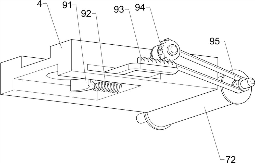
[0034] On the basis of Example 1, such as image 3 , Figure 4 , Figure 5 , Figure 6 and Figure 7 As shown, a feeding mechanism 7 is also included, and the feeding mechanism 7 includes a first rotating rod 71, a first transmission wheel assembly 72, a ratchet gear 73, a first ratchet bar 74, a first connecting rod 75, a block 76, a first Two springs 77, the third connecting block 78, the lower pressing rod 79, the third spring 710 and the second guide rod 711, the left side of the base 1 top symmetrical rotation type is provided with the first rotating rod 71, and the first rotating rod 71 is provided with There is a first transmission wheel assembly 72, the first transmission wheel assembly 72 is composed of rollers and conveyor belts, the rollers are respectively connected to the first rotating rod 71, the conveyor belt is connected between the rollers, and the outer front side of the first rotating rod 71 on the right is provided with A ratchet gear 73, a third conne...


PUM


Abstract

The invention relates to round hole punching equipment, in particular to metal straight bar round hole punching equipment. The metal straight bar round hole punching equipment has a waste collecting function and does not need to manually push materials. According to the technical scheme, the metal straight bar round hole punching equipment comprises a base, a supporting table, a fixing mechanism, a downward pressing mechanism, an air cylinder and an extrusion column; the supporting table is arranged at the top of the base; the fixing mechanism is arranged at the top of the supporting table; the downward pressing mechanism is arranged at the top of the fixing mechanism; the air cylinder is arranged at the top of the downward pressing mechanism; and the extrusion column is arranged at the bottom of the downward pressing mechanism, and the extrusion column is connected with the fixing mechanism in a sliding mode. A straight metal bar is placed on the supporting table by people, the straight metal bar is fixed under the action of the fixing mechanism, then the air cylinder is started, the downward pressing mechanism is driven under the action of a piston rod of the air cylinder to drive the extrusion column to move downwards, and the straight metal bar is punched through the extrusion column.

Description

technical field [0001] The invention relates to a round hole punching device, in particular to a metal straight round hole punching device. Background technique [0002] In the general metal straight bar processing process, people need to punch a plurality of round holes on the metal straight bar, so that people can process the metal straight bar later. [0003] Currently on the market, most of the straight metal punching machines still have some deficiencies. Most of the straight metal punching machines are usually punched by people manually placing the metal straight strips on the punching machine. If you are not careful, the punching machine is easy to hurt people's hands, which poses a safety hazard, and the punching effect of the metal straight strip is not good. Workload, so that people's work efficiency is not high and other problems exist. [0004] To sum up, it is necessary to design a metal straight bar punching equipment that has the function of collecting waste...

Claims


Application Information

Patent Timeline
Patent Type & Authority Applications(China)
IPC IPC(8): B21D28/24B21D43/00B21D45/02
CPCB21D28/24B21D43/003B21D45/003B21D45/02Y02P70/10
Inventor 何佳雄
Owner 朝阳市多元合金铸造有限责任公司
Learn More