
A kind of auxiliary device for pin welding of printed circuit board

A technology for printed circuit boards and auxiliary devices, which is applied in the direction of auxiliary devices, printed circuits, and printed circuit manufacturing. Achieve the effect of increasing the bonding sealing area, increasing the overall structural strength, and preventing pollution and corrosion

Active Publication Date: 2022-07-22
SUZHOU METABRAIN INTELLIGENT TECH CO LTD
View PDF6 Cites 0 Cited by
  • Summary
  • Abstract
  • Description
  • Claims
  • Application Information

AI Technical Summary

Problems solved by technology

[0007] In order to solve the problem that some volatile substances in the flux of current wave soldering are easy to volatilize in the high-temperature wave soldering liquid to form a gaseous or liquid state, thereby forming the above-mentioned soldering pollutants, which will enter the printed circuit board along the pin hole The front of the circuit board, or along the pins of the component enters the interior of the component body, causing the component to fail; the pollutants on the front of the printed circuit board can be scattered to any position on the front of the printed circuit board, and there are risks of circuit short circuit and corrosion, which will cause The function of the printed circuit board is abnormal, and the welding pollutants adhere to the component pins for a long time, which will cause pollution and corrosion to the component pins, which will lead to the problem of abnormal function of the component. The invention provides a printed circuit board lead Foot Welding Aid

Method used


Image

  • A kind of auxiliary device for pin welding of printed circuit board
  • A kind of auxiliary device for pin welding of printed circuit board
  • A kind of auxiliary device for pin welding of printed circuit board

Examples


Embodiment Construction

[0026] In order to make the objects, features and advantages of the present invention more obvious and understandable, the technical solutions in the present invention will be clearly and completely described below with reference to the accompanying drawings in the specific embodiments. Obviously, the implementation described below Examples are only some embodiments of the present invention, but not all embodiments. Based on the embodiments in this patent, all other embodiments obtained by persons of ordinary skill in the art without creative efforts shall fall within the scope of protection of this patent.

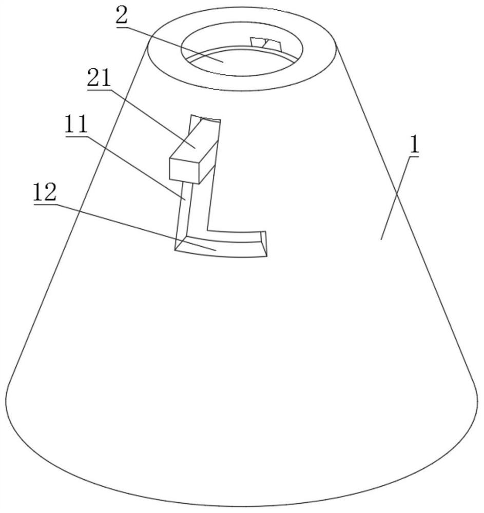
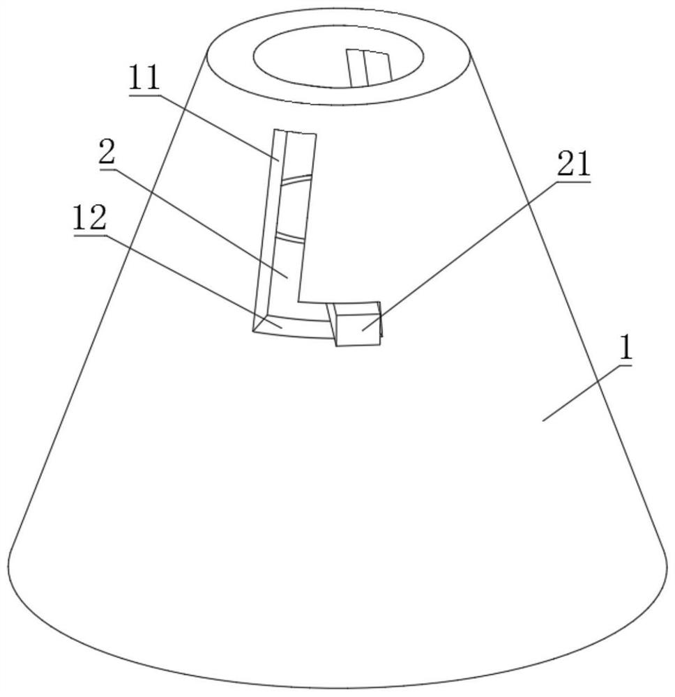
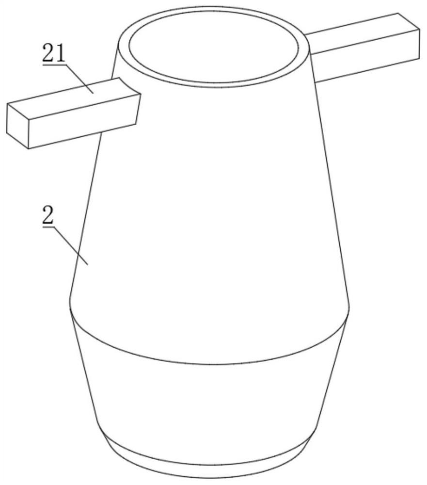
[0027] like Figure 1-4 As shown, the present invention discloses an auxiliary device for pin welding of printed circuit boards, comprising an outer sleeve 1 made of high temperature resistant insulating material and an inner blocking cylinder 2, and the inner blocking cylinder 2 is vertically slidably arranged on the outer sleeve 1 Inside; the outer sleeve 1 is in the s...


PUM

PropertyMeasurementUnit
diameteraaaaaaaaaa
surface areaaaaaaaaaaa

Abstract

The invention discloses an auxiliary device for soldering pins of printed circuit boards, belonging to the technical field of soldering pins of circuit boards. The lower part of the inner baffle is supported on the upper edge of the pin hole of the circuit board. During the wave soldering process, the tin liquid flows upward through the gap between the pin and the pin hole, and is attached to the upper edge of the pin hole through the inner baffle tube, which can block the tin liquid overflowing upward and ensure the welding quality; and cooperate with the lower end of the outer sleeve It is attached to the surface of the circuit board to effectively prevent the contaminants from spreading and scattering around the surface of the circuit board; and is fastened with the pins through the small mouth end of the outer sleeve to prevent the contaminants from moving up along the pins and prevent the contaminants from entering. Inside the parts, the welding quality and welding safety are guaranteed; the overall structure is simple, the cost is low, the realization is easy, and the practicability is good.

Description

technical field [0001] The invention belongs to the technical field of circuit board pin welding, in particular to a printed circuit board pin welding auxiliary device. Background technique [0002] With the development of high technology, it is necessary to improve the function and performance of electronic products. The highly integrated process requirements make the printed circuit board more and more small and fine, and there are more and more stringent requirements for the surface technology of the device. [0003] The plug-in components need to adopt the wave soldering process, and the wave soldering is due to the particularity of the process, that is, the wave soldering is to make the soldering surface of the printed circuit board directly contact with the high-temperature liquid tin to achieve the purpose of welding. The device makes the liquid tin form a wave-like shape, which has a certain impact on the printed circuit board. [0004] During wave soldering, some c...

Claims


Application Information

Patent Timeline
Patent Type & Authority Patents(China)
IPC IPC(8): B23K1/08B23K3/08H05K3/34
CPCB23K1/085B23K3/08H05K3/3421
Inventor 于浩
Owner SUZHOU METABRAIN INTELLIGENT TECH CO LTD
Learn More