
Pressing energy storage rebound mechanism

A rebound mechanism and energy storage technology, applied in the direction of building components, building structures, applications, etc., can solve problems affecting the stability of furniture products, affecting the overall appearance of furniture products, occupying the space position of furniture products, etc., to achieve the benefit of the overall Simple setting, convenient daily use and maintenance, and the effect of reducing space location

Pending Publication Date: 2021-11-05
GUANGDONG DTC HARDWARE PRECISION MFG CO LTD
View PDF1 Cites 0 Cited by
  • Summary
  • Abstract
  • Description
  • Claims
  • Application Information

AI Technical Summary

Problems solved by technology

Although the above-mentioned structure can realize the effect of pressing the furniture to open and close, and each device automatically resets when the furniture is opened and closed, it is necessary to arrange multiple components and devices on the furniture product, and through these components and devices to cooperate with each other, and through the furniture. The pressing effect of the door panel can achieve the above effect. Its structure is quite complicated and the production cost is quite high. If the assembly position between the component and the device is not accurate, or the displacement occurs during use, the corresponding function cannot be realized, which will affect the furniture. Stability in use of the product; at the same time, due to the need for the pressing effect of the furniture door panel, the entire pressing rebound structure needs to extend out of the furniture product to interact with the furniture door panel, which not only occupies the space position of the furniture product, but also affects the overall appearance of the furniture product

Method used


Image

  • Pressing energy storage rebound mechanism
  • Pressing energy storage rebound mechanism
  • Pressing energy storage rebound mechanism

Examples


Embodiment Construction

[0039] The present invention will be further described below in conjunction with the accompanying drawings and embodiments.

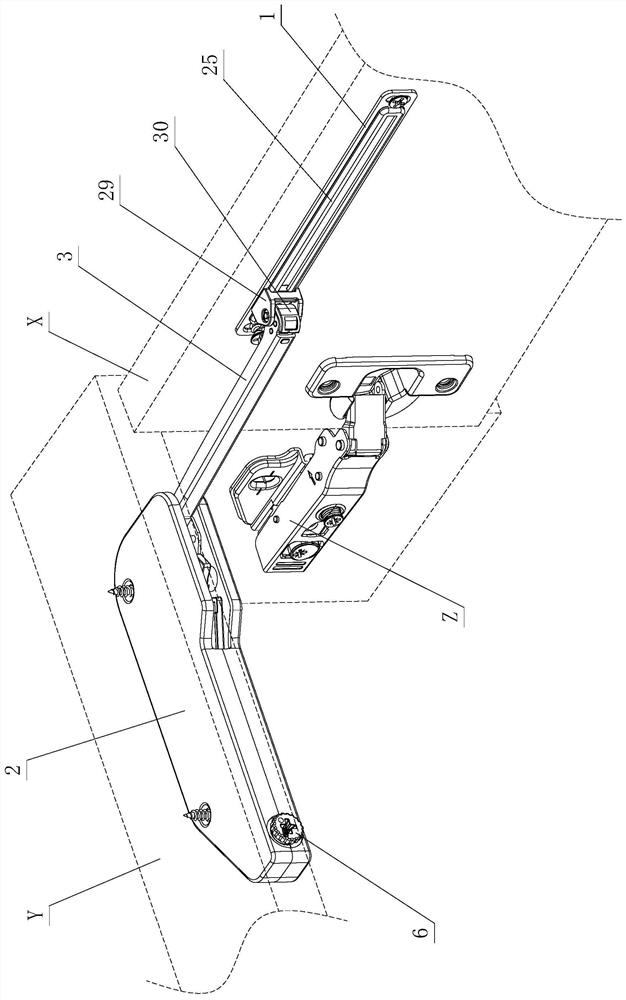
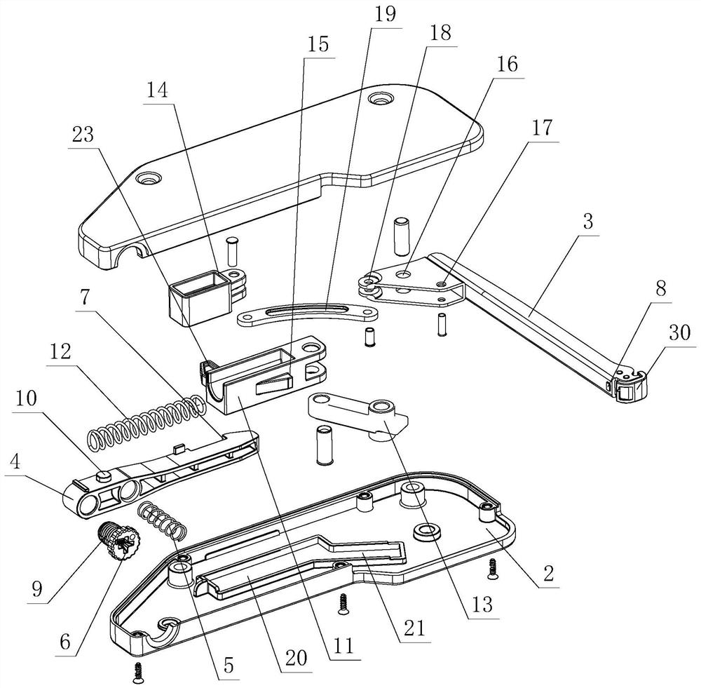
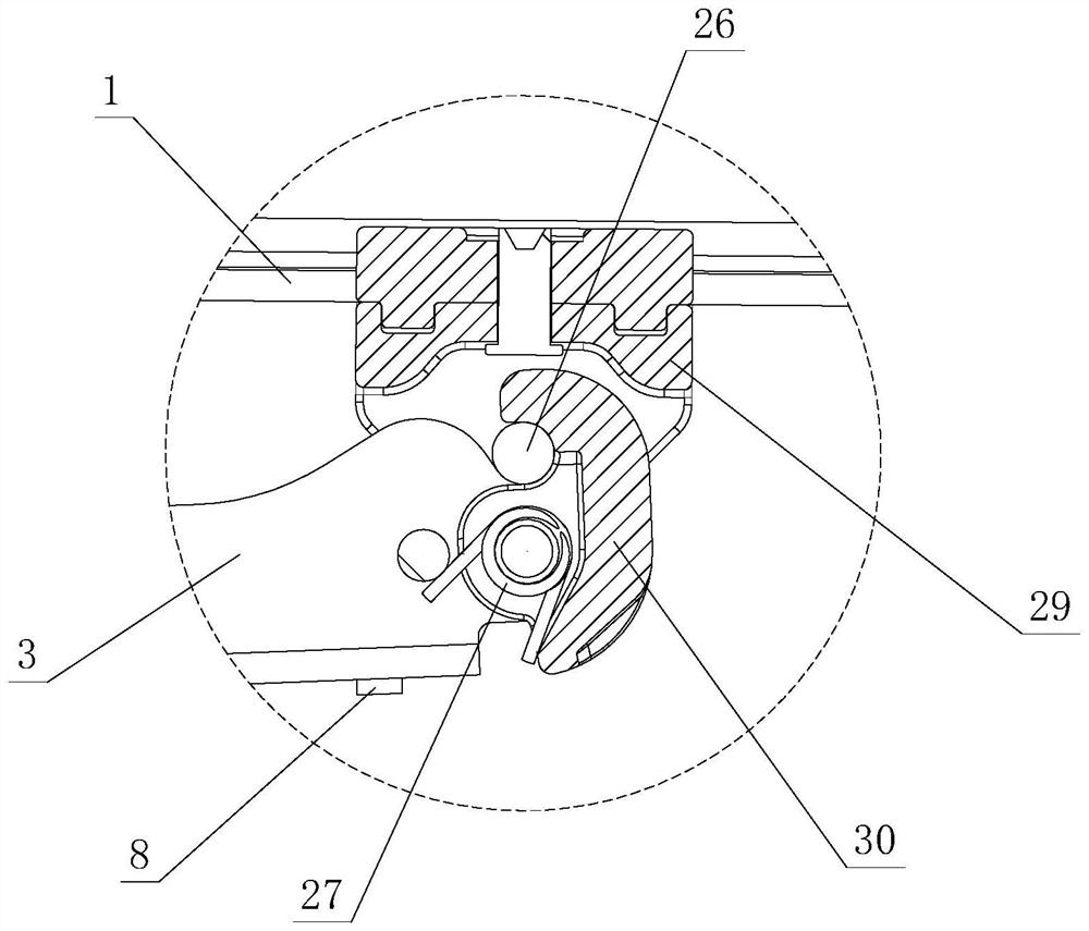
[0040] see Figure 1-Figure 13 , the pressing energy storage rebound mechanism includes a rebound device and an assembly element 1; the rebound device includes a bracket element 2, and the bracket element 2 is provided with a pressing assembly, a pushing assembly and a connecting arm 3; the pressing assembly and the pushing assembly are independent of each other set, and elastically move on the support element 2 respectively; the connecting arm 3 is hinged to open and close on the support element 2, and a transmission assembly is arranged on it, and is driven and connected to each other through the transmission assembly and the push assembly; the connection arm 3 A disassembly assembly is provided between the assembly element 1, and the two are disassembled and connected through the disassembly assembly; the connecting arm 3 slides on the assembly eleme...


PUM


Abstract

The invention relates to a pressing energy storage rebounding mechanism. The pressing energy storage rebounding mechanism comprises a rebounding device and an assembling element; the rebounding device comprises a support element; a pressing assembly, a pushing assembly and a connecting arm are arranged on the support element; the pressing assembly and the pushing assembly are independently arranged and elastically move on the support element; the connecting arm is hinged to the support element in an opening and closing mode, is provided with a transmission assembly and is in driving connection with the pushing assembly through the transmission assembly; a dismounting and moving assembly is arranged between the connecting arm and the assembling element; the connecting arm and the assembling element are detachably connected through the dismounting and moving assembly; the connecting arm slides on the assembling element through the dismounting and moving assembly when being hinged to the support element in an opening and closing mode; the connecting arm, and / or the assembling element, and / or the dismounting and moving assembly and the pressing assembly are mutually pressed to drive the pressing assembly and the pushing assembly to be mutually locked or unlocked; and the pushing assembly elastically moves on the support element when being unlocked, and drives the connecting arm to be automatically hinged and opened to a certain position relative to the support element through the transmission assembly. The practicability is high.

Description

technical field [0001] The invention relates to a pressing energy storage rebound mechanism. Background technique [0002] The applicant's patent document number is CN211883005U, and on November 10, 2020, an adjustable furniture firm pressing and rebounding structure was disclosed. The movable part and the pressing function assembly are provided with a pressing rebound device on the fixed slide rail; the pressing function assembly includes a pressing bracket and an adjusting part, the pressing bracket is fixedly arranged on the moving slide rail, and the adjusting part is adjustable and movable arranged on the pressing bracket, and Mutual pressing and rebounding effect with the pressing rebound device; the moving slide rail is driven to slide on the fixed sliding rail through a tool or manual action, and the moving slide rail automatically slides open through the interaction between the adjustment part and the pressing rebound device when sliding. On the fixed slide rail; b...

Claims


Application Information

Patent Timeline
Patent Type & Authority Applications(China)
IPC IPC(8): E05F1/10E05F1/12E06B5/00E06B7/28A47B96/20A47B97/00
Inventor 伍志勇
Owner GUANGDONG DTC HARDWARE PRECISION MFG CO LTD
Learn More