Control structure suitable for large-diameter steam turbine steam extraction valve and control method

A control structure and steam turbine technology, applied in the direction of valve operation/release device, valve details, valve device, etc., can solve the problems of spring barrel failure, disc spring leaf breakage, etc., to avoid high temperature blow damage and ensure safety , the effect of reducing the length of the movement

Pending Publication Date: 2021-11-05
HUANENG YIMIN COAL POWER CO LTD
View PDF0 Cites 0 Cited by
  • Summary
  • Abstract
  • Description
  • Claims
  • Application Information

AI Technical Summary

Problems solved by technology

[0002] The disc springs accumulated by a single piece are processed into a disc spring barrel composed of dozens of disc springs as the actuator. Since the disc springs in the disc spring barrel are composed of a single piece, even one or several disc springs Even if the shaped spring breaks, it will not cause a large hysteresis effect on the closing time of the valve. The butterfly spring is particularly sensitive to high-temperature steam. The structure of the existing technology makes the high-temperature steam blow directly to the butterfly spring for a long time. A large area of ​​fracture occurs, rendering the entire spring barrel useless

Method used


Image

  • Control structure suitable for large-diameter steam turbine steam extraction valve and control method

Examples


Embodiment 1

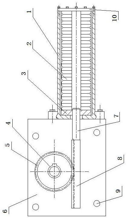
[0021] A control structure suitable for steam extraction valves of large-diameter steam turbines, which consists of: a controller box 6, a gear 5 is installed inside the controller box, and the inner hole of the gear is connected to the valve stem through a flat key 4 connection, the gear is meshed with the rack 8, the left end of the rack is fixed with the guide rod 7, and the guide rod passes through the side wall of the controller box and is threadedly connected with the backing plate 3, so The right side of the backing plate is attached to a set of butterfly springs 2 in sequence, a set of butterfly springs and the backing plate are installed inside the spring barrel 1, and the connecting valve stem is connected to the electric hydraulic cylinder .

Embodiment 2

[0023] According to the control structure applicable to the steam extraction valve of a large-diameter steam turbine described in Embodiment 1, one end of the spring tube is connected to the controller box through a bolt, and the other end of the spring tube is connected to the end cover 10 through a bolt. There is a group of exhaust and drainage holes 9 on the side walls around the controller box.

Embodiment 3

[0025] The control method applicable to the control structure of the large-bore steam turbine extraction valve described in embodiment 1 or 2, the method may further comprise the steps:

[0026] First, install the disc spring in the vertical direction of the connecting valve stem of the butterfly valve, select the number of disc springs that meet the fast closing quantity of the butterfly valve according to the torque of the butterfly valve, and the radius of the thrust rod and the gear is the connecting valve 1.5-2 times the rod radius;

[0027] A toothed groove is machined on the connecting stem of the butterfly valve or a small gear is installed on the finished processed stem in the form of rack and pinion meshing, or a gear perpendicular to the valve stem can be machined or installed The thrust rod of the rod uses the guide rod protruding from the spring barrel to push the rack or thrust rod to make the valve move;

[0028] When the butterfly valve is opened, the electric...


PUM


Abstract

The invention relates to a control structure suitable for a large-diameter steam turbine steam extraction valve and a control method. According to the structure arranged in the prior art, high-temperature steam directly blows a belleville spring piece for a long time, the belleville spring piece is fractured in a large area, and a whole spring barrel is out of action. The structure comprises a controller box body (6), a gear (5) is installed in the controller box body, an inner hole of the gear is connected with a connecting valve rod (4) through a flat key, the gear is meshed with a rack (8), the left end of the rack is fixed to a guide rod (7), the guide rod penetrates through the side wall of the controller box body and is connected with a base plate (3) through threads, the right side of the base plate is sequentially attached to a set of belleville springs (2), the belleville springs and the base plate are installed in a spring barrel (1), and the connecting valve rod is connected with an electric hydraulic cylinder. The control structure is suitable for the large-diameter steam turbine steam extraction valve.

Description

technical field [0001] The invention relates to a control structure and control method suitable for steam extraction valves of large-diameter steam turbines. Background technique [0002] The disc springs accumulated by a single piece are processed into a disc spring barrel composed of dozens of disc springs as the actuator. Since the disc springs in the disc spring barrel are composed of a single piece, even one or several disc springs Even if the shaped spring breaks, it will not cause a large hysteresis effect on the closing time of the valve. The butterfly spring is particularly sensitive to high-temperature steam. The structure of the existing technology makes the high-temperature steam blow directly to the butterfly spring for a long time. A large area fracture occurs, rendering the entire spring barrel useless. Therefore, how to prevent the actuator of the disc spring barrel from blowing the high-temperature steam leaked from the valve stem directly into the disc spr...

Claims


Application Information

Patent Timeline
Patent Type & Authority Applications(China)
IPC IPC(8): F16K31/54F16K31/12F16H57/027F01D17/10
CPCF16K31/54F16K31/12F16H57/027F01D17/10
Inventor 马静波郑安李德永杨立勇关志宏林凯
Owner HUANENG YIMIN COAL POWER CO LTD
Why Eureka
Try Eureka