Liquid cooling plate integrated box body and battery box

An integrated, liquid-cooled plate technology, applied in the direction of secondary batteries, battery pack components, circuits, etc., can solve the problems of increased temperature difference between batteries, low production and installation efficiency, complicated procedures, etc., to reduce temperature rise and temperature difference , Reduce the assembly process and reduce the overall weight

Pending Publication Date: 2021-11-05
HUBEI JINQUAN NEW MATERIALS CO LTD
View PDF0 Cites 1 Cited by
  • Summary
  • Abstract
  • Description
  • Claims
  • Application Information

AI Technical Summary

Problems solved by technology

At present, the commonly used liquid cooling method usually adopts the combined assembly design of the liquid cooling plate and the box body. The structure of the assembly of the liquid cooling plate and the box body needs to fix the liquid cooling plate in the box to be assembled, and the box to be assembled needs to be pre-assembled. Leave enough space for the liquid cold plate to be placed, but fixing the liquid cold plate in the box requires bolts and other fixing parts for fixing, and the upper surface of the liquid cold plate is also provided with a heat conduction pad, resulting in many assembly parts in the battery box , heavy weight, large size, uncompact design, complex procedures during assembly, and low production and installation efficiency
On the other hand, for the current path of the coolant flow channel of the existing battery box, the overall temperature of the battery box rises and the temperature difference during the cooling process is large. With the increase of the charge and discharge rate and the extension of the working time, The temperature difference between batteries will further increase, which will affect the overall cycle life, system capacity, etc.

Method used


Image

  • Liquid cooling plate integrated box body and battery box
  • Liquid cooling plate integrated box body and battery box
  • Liquid cooling plate integrated box body and battery box

Examples


Embodiment Construction

[0034] The following will clearly and completely describe the technical solutions in the embodiments of the present invention with reference to the accompanying drawings in the embodiments of the present invention. Obviously, the described embodiments are only some, not all, embodiments of the present invention. Based on the embodiments of the present invention, all other embodiments obtained by persons of ordinary skill in the art without creative efforts fall within the protection scope of the present invention.

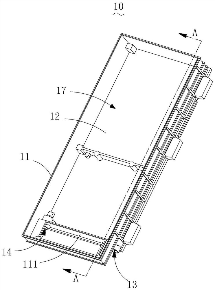
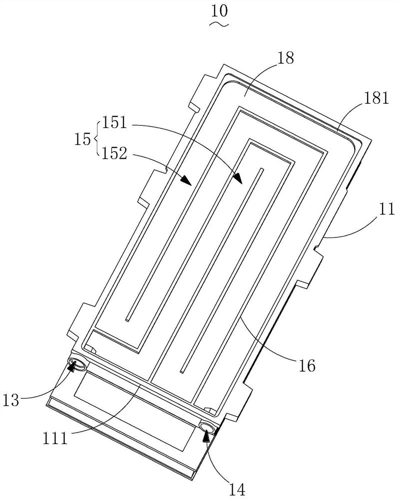
[0035] The present invention provides a liquid cold plate integrated box 10, such as Figure 1-10 As shown, this liquid cold plate integrated box 10 is mainly used for a new battery box 100, figure 1 A schematic diagram of the three-dimensional structure of the liquid-cooled plate integrated box in the embodiment of the present invention is shown. The liquid-cooled plate integrated box 10 includes a box body 11 and a bottom plate 12. The box body 11 includes a side...


PUM


Abstract

The invention provides a liquid cooling plate integrated box body and a battery box. The liquid cooling plate integrated box body comprises a box body and a bottom plate, the box body comprises a side plate forming an accommodating space with the bottom plate, a cooling liquid inlet and a cooling liquid outlet, and a flow channel from the cooling liquid inlet to the cooling liquid outlet is formed in the box body based on the side plates and the bottom plate. According to the liquid cooling plate integrated box body provided by the invention, the liquid cooling plate integrated box body can be compactly designed, so that the size of the battery box is reduced, meanwhile, the overall weight of the box body is reduced, the assembly process is reduced, and the production and installation efficiency is improved.

Description

technical field [0001] The invention relates to the technical field of new energy storage battery boxes, in particular to a liquid-cooled plate integrated box body and a battery box. Background technique [0002] With the development of the national economy and increasingly stringent environmental requirements, the new energy electric vehicle industry has received strong support to promote the rapid development of the industry. Among them, the power battery, as the main energy storage component, needs to be focused on in the design and development of new energy electric vehicles. The power battery will undergo certain charging and discharging behaviors during the use of the car, and will be accompanied by battery heating. In order to ensure the overall performance and service life of the power battery, the heat generated by the power battery needs to be dissipated in time. [0003] At present, the heat dissipation methods for batteries mainly include natural cooling, air co...

Claims


Application Information

Patent Timeline
Patent Type & Authority Applications(China)
IPC IPC(8): H01M10/613H01M10/625H01M10/6554H01M10/6556H01M10/617H01M10/6568H01M50/244H01M50/249H01M50/209H01M50/258
CPCH01M10/613H01M10/625H01M10/6554H01M10/6556H01M10/617H01M10/6568H01M50/244H01M50/249H01M50/209H01M50/258Y02E60/10
Inventor 蔡鹏阎明瀚肖鹏丁涛江吉兵
Owner HUBEI JINQUAN NEW MATERIALS CO LTD
Why Eureka
Try Eureka