Supercharge Your Innovation With Domain-Expert AI Agents!

Automatic speed control non-contact magnetic coupling piezoelectric wind energy collector

A non-contact, magnetic coupling technology, which is applied in the field of energy harvesting, can solve the problems of output energy reduction and achieve the effects of improving service life, avoiding output energy reduction, and avoiding premature fragmentation

Active Publication Date: 2021-11-05
西北工业大学太仓长三角研究院 +1
View PDF5 Cites 0 Cited by
  • Summary
  • Abstract
  • Description
  • Claims
  • Application Information

AI Technical Summary

Problems solved by technology

For example, in 2019, Zhou Zhiyong proposed a piezoelectric wind energy harvester in his paper "Dynamic Multi-stable Piezoelectric Wind Energy Harvesting Structure Design and Experimental Verification". Due to the deviation of the piezoelectric vibration frequency from the natural frequency, the output energy is reduced; in 2019, Bai Fengxian proposed multiple piezoelectric array wind energy harvesters with magnetic beams in his paper "Research on the Characteristics of Non-contact PVDF Piezoelectric Cantilever Wind Energy Harvesting System". The output power is the most when the wind speed is 3.5-5m / s, but as the wind speed increases, the output energy decreases because the piezoelectric vibration frequency deviates from the natural frequency

Method used


Image

  • Automatic speed control non-contact magnetic coupling piezoelectric wind energy collector
  • Automatic speed control non-contact magnetic coupling piezoelectric wind energy collector
  • Automatic speed control non-contact magnetic coupling piezoelectric wind energy collector

Examples


Embodiment Construction

[0025] In describing the present invention, it should be understood that the terms "center", "longitudinal", "transverse", "length", "width", "thickness", "upper", "lower", "front", " Orientation indicated by rear, left, right, vertical, horizontal, top, bottom, inside, outside, clockwise, counterclockwise, etc. The positional relationship is based on the orientation or positional relationship shown in the drawings, which is only for the convenience of describing the present invention and simplifying the description, rather than indicating or implying that the referred device or element must have a specific orientation, be constructed and operated in a specific orientation, Therefore, it should not be construed as limiting the invention.

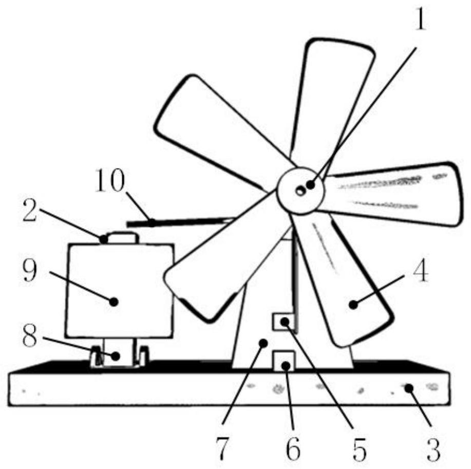
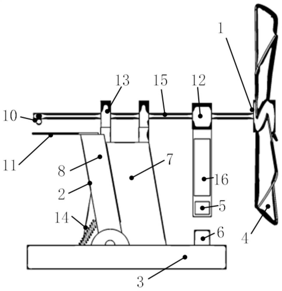
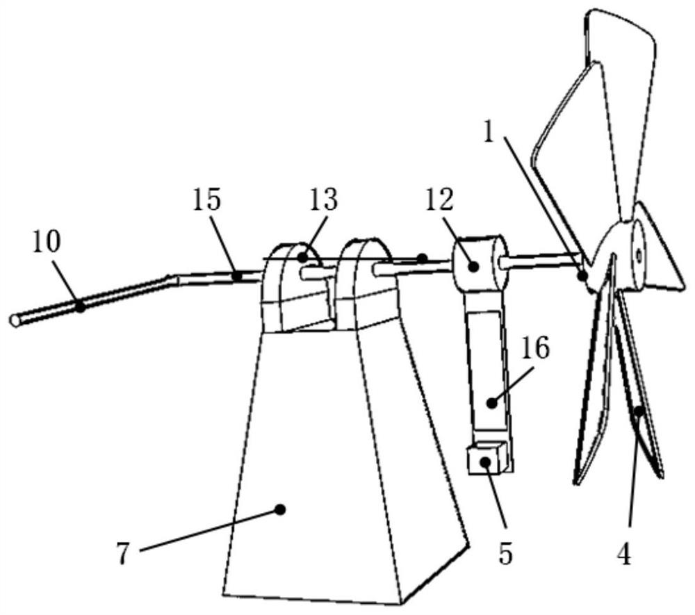
[0026] see Figure 1-Figure 6 , the present invention includes an energy collection structure 1, an automatic speed control assembly 2 and a base 3, the energy collection structure 1 is rotatably connected to a support 7, the support 7 is f...


PUM


Abstract

The invention relates to an automatic speed control non-contact magnetic coupling piezoelectric wind energy collector which comprises an energy collection structure, a speed control structure and a base. The bottom ends of the energy collection structure and the speed control structure are connected with the base, a square permanent magnet of the energy collection structure is in non-contact magnetic coupling with an excitation permanent magnet on the base, and the energy collection structure is composed of a fan blade, a piezoelectric plate, the square permanent magnet, a rotating shaft and a cylindrical shell. The fan blade is fixed at the front end of the rotating shaft, and the piezoelectric plate is fixed at the middle tail end of the rotating shaft and is adhered with the square permanent magnet. Compared with the prior art, the stress mode of the piezoelectric plate is non-contact magnetic coupling, and the service life of the piezoelectric plate can be prolonged. According to the invention, maximum energy collection can be achieved at a lower wind speed, and energy can be obtained at an optimal rotating speed section by automatically controlling the rotating speed at a high wind speed, namely considerable energy can be collected in a wide wind area.

Description

technical field [0001] The invention belongs to the field of energy harvesting, in particular to a self-controlled speed non-contact magnetic coupling piezoelectric wind energy collector. Background technique [0002] With the popularization of 5G and the advent of the era of intelligent Internet of Things, the demand for sensors has risen sharply, and the power supply has become one of the problems that need to be solved urgently. Due to the large number of sensors, and some sensors are located in high places, underground or inaccessible places, manual replacement of batteries on a regular basis will undoubtedly greatly increase operating costs and waste social resources. Self-capturing technology has become the best way to solve this problem. [0003] The piezoelectric harvester has the advantages of simple structure and high energy density, and has become a hot research topic. Traditional piezoelectric harvesters are mostly direct contact, such as knocking, and piezoele...

Claims


Application Information

Patent Timeline
Patent Type & Authority Applications(China)
IPC IPC(8): H02N2/18H02K49/10F03D9/25F03D9/11F03D7/02
CPCH02N2/185H02K49/102F03D9/25F03D9/11F03D7/0276Y02E70/30Y02E10/72
Inventor 陈楠王伊榛魏廷存
Owner 西北工业大学太仓长三角研究院
Features
  • R&D
  • Intellectual Property
  • Life Sciences
  • Materials
  • Tech Scout
  • Unparalleled Data Quality
  • Higher Quality Content
  • 60% Fewer Hallucinations
Learn More