Electric power fitting laser strengthening device and method

A technology of laser strengthening and electric fittings, which is applied in the field of electric fittings processing, can solve the problems of large volume of laser strengthening devices, low efficiency of strengthening methods, and high utilization rate of laser, and achieve simple structure, simple and convenient operation, and high utilization rate of laser Effect

Pending Publication Date: 2021-11-09
ELECTRIC POWER SCI RES INST OF STATE GRID XINJIANG ELECTRIC POWER +1
View PDF6 Cites 0 Cited by
  • Summary
  • Abstract
  • Description
  • Claims
  • Application Information

AI Technical Summary

Problems solved by technology

[0004] The purpose of the present invention is to overcome the problems of large volume, complicated operation, low strengthening method efficiency and low laser utilization rate of the prior art laser strengthening device, and provide a laser strengthening device and method for electric power fittings, which have simple structure, simple operation and high strengthening efficiency , high utilization rate of laser

Method used


Image

  • Electric power fitting laser strengthening device and method
  • Electric power fitting laser strengthening device and method
  • Electric power fitting laser strengthening device and method

Examples


Embodiment 1

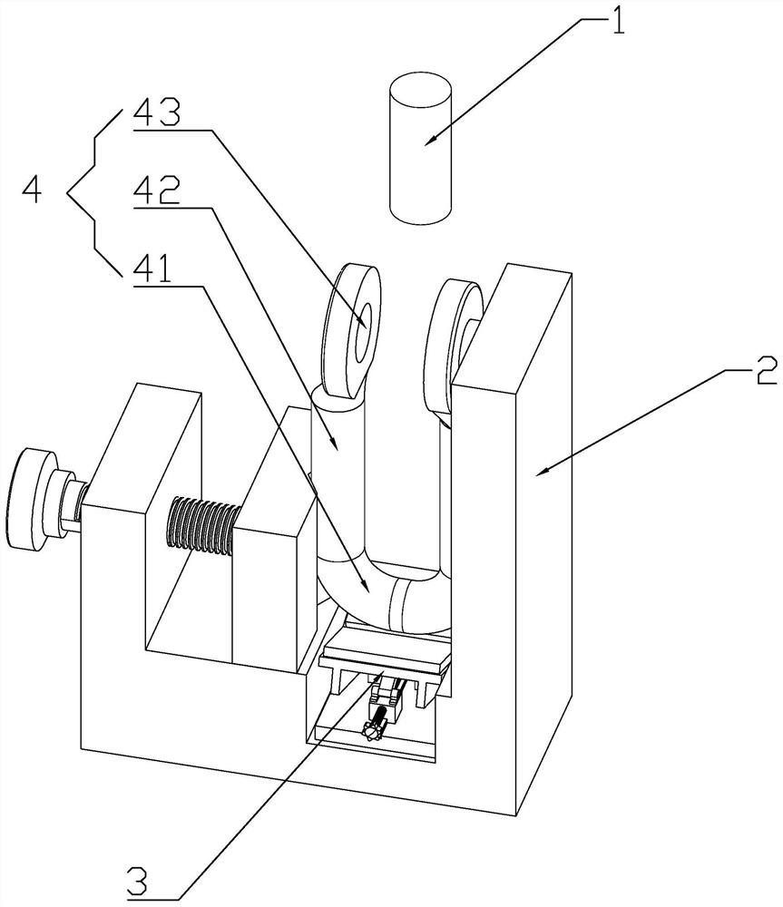
[0041] Such as figure 1 As shown, a laser strengthening device for electric power fittings is used for laser strengthening the U-shaped ring 4. The U-shaped ring 4 is a symmetrical structure, including an arc segment 41 at the bottom, and both ends of the arc segment 41 extend upward to form a vertical The vertical section 42 of the vertical section, the cross section of the arc section 41 and the vertical section 42 is circular, and the top of the vertical section 42 forms an ear upwards, and the ear is provided with a circular suspension hole 43, between the vertical sections 42 The circumferential direction of the arc section 41 is the area to be strengthened. Enhancements include:

[0042] The laser strengthening head 1 is arranged vertically downward, and is used to emit laser light to the strengthening area of ​​the electric fitting;

[0043] The clamping device 2 is used to fix and clamp the power fittings so that the laser can be directed to the strengthened area;

...

Embodiment 2

[0051] A laser strengthening method for electric metal fittings, comprising the steps of:

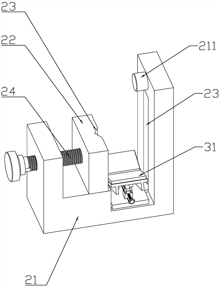
[0052] S1. Fix the U-shaped ring on the clamping device 2, in which the hanging hole 43 on one side is suspended on the limit boss 211 for Z-direction positioning, and the fixed screw 24 is rotated to move the slider 22 to clamp the U-shaped ring from both sides. Ring, the vertical section of the U-shaped ring is attached to the V-shaped grooves on both sides and the laser emitted by the laser strengthening head 1 is aimed at the strengthening area in the middle of the arc section, and the size of the laser spot is set. The long axis (perpendicular to The length of the horizontal axis of the arc segment) is twice the diameter of the arc segment, and the length of the minor axis (parallel to the horizontal axis of the arc segment) is the distance of the vertical segment 42;

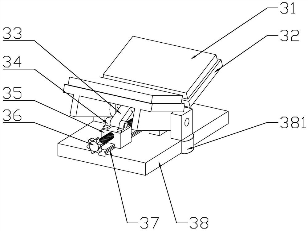
[0053] S2. Turn the ball screw 36 to adjust the position of the reflective surface of the reflector 3 to ensure t...


PUM


Abstract

The invention discloses an electric power fitting laser strengthening device and method. The device comprises a laser strengthening head which is used for transmitting laser to a strengthening area of an electric power fitting, a clamping device and a reflecting device. The clamping device is used for fixedly clamping the electric power fitting to enable the laser to be transmitted to the strengthening area; and the reflecting device is used for reflecting the laser to the strengthening area which cannot be directly irradiated by the laser, and the strengthening area is arranged between the reflecting surface of the reflecting device and the laser strengthening head. The device has the following beneficial effects: (1) the reflecting device is arranged to realize omni-directional irradiation at one time, and the efficiency is high; (2) the part of laser spots exceeding the strengthening area can be reflected to the strengthening area by the reflecting device, and the laser utilization rate is high; (3) the angle of the reflecting device is adjustable, the laser irradiation is sufficient and uniform, and the product surface quality is high; (4) by arranging the clamping device, the electric power fitting is rapidly and stably fixed; and (5) the structure is simple, and use and operation are easy and convenient.

Description

technical field [0001] The invention relates to the technical field of electric power fittings processing, in particular to a laser strengthening device and method for electric power fittings. Background technique [0002] The transmission lines in many areas of the country are seriously affected by strong winds, which causes some stressed parts on the power transmission equipment to bear huge forces, resulting in wear and tear of the parts. Fittings such as U-shaped rings are worn to varying degrees, and the proportion of worn parts is as high as 10%. Taking the U-shaped ring as an example, the U-shaped ring includes a circular arc section at the bottom of the middle, and the two ends of the circular arc section extend to the same side to form a cylindrical section. Fortified area. Since the circumferential direction of the arc section of the U-shaped ring needs to be strengthened, and the laser is transmitted in a straight line, the existing laser strengthening method us...

Claims


Application Information

Patent Timeline
IPC IPC(8): C21D10/00
CPCC21D10/005
Inventor 王欣欣张陵何成张博魏晌庄凌志赵建平金杨福谢颂伟
Owner ELECTRIC POWER SCI RES INST OF STATE GRID XINJIANG ELECTRIC POWER
Why Eureka
Try Eureka