
Low power apparatus and method to multiply frequency of a clock

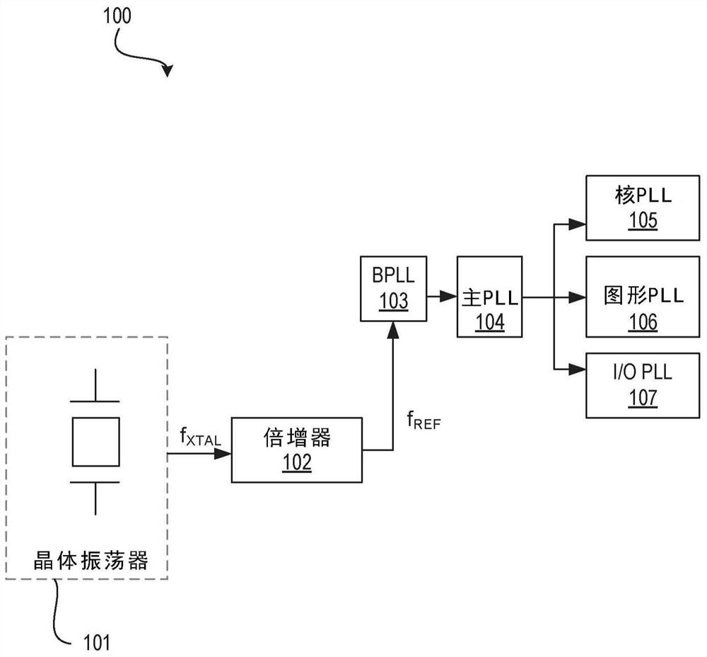
A clock frequency multiplication and frequency technology, applied in the direction of automatic power control, pulse technology, pulse processing, etc., can solve the problems of increasing the quantization noise of the PLL frequency divider, increasing the PLL noise, and high loop filter capacitor layout area.

Pending Publication Date: 2021-11-09
INTEL CORP
View PDF0 Cites 0 Cited by
  • Summary
  • Abstract
  • Description
  • Claims
  • Application Information

AI Technical Summary

Problems solved by technology

For a given PLL output frequency, low f REF The feedback divider ratio (N) is increased, thereby 1) increasing the phase-frequency detector (PFD) and charge pump noise of the PLL, and 2) due to the delta-sigma modulator in the fractional-N mode of the divider ( delta-sigma modulator), which increases the quantization noise of the PLL divider
A lower f REF also results in higher loop filter capacitance and its layout area

Method used


Image

  • Low power apparatus and method to multiply frequency of a clock
  • Low power apparatus and method to multiply frequency of a clock
  • Low power apparatus and method to multiply frequency of a clock

Examples


example 1

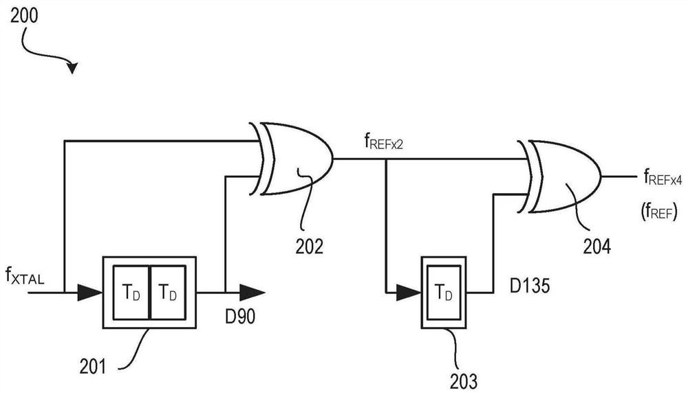
[0103] Example 1: An apparatus comprising: a duty cycle correction (DCC) circuit for receiving a first clock having a first frequency to generate an output substantially corrected for a duty cycle error; and a multiplier circuit coupled to an output of a DCC circuit, wherein the multiplier circuit is used to generate a second clock having a second frequency higher than the first frequency, wherein the multiplier circuit includes a delay line for delaying the output of the DCC circuit and generating a phase shifted signal ; and a comparator for comparing the output of the DCC circuit with the phase-shifted signal.

example 2

[0104] Example 2: The apparatus of Example 1, wherein the delay line is a first delay line, wherein the phase shifted signal is a first phase shifted signal, and wherein the multiplier circuit comprises a second delay line for delaying the first phase shifted signal and generate a second phase-shifted signal.

example 3

[0105] Example 3: The apparatus of Example 2, wherein the multiplier circuit comprises: an inverter to invert the second phase-shifted signal; and a phase detector to receive the output of the inverter and the output of the DCC circuit.


PUM


Abstract

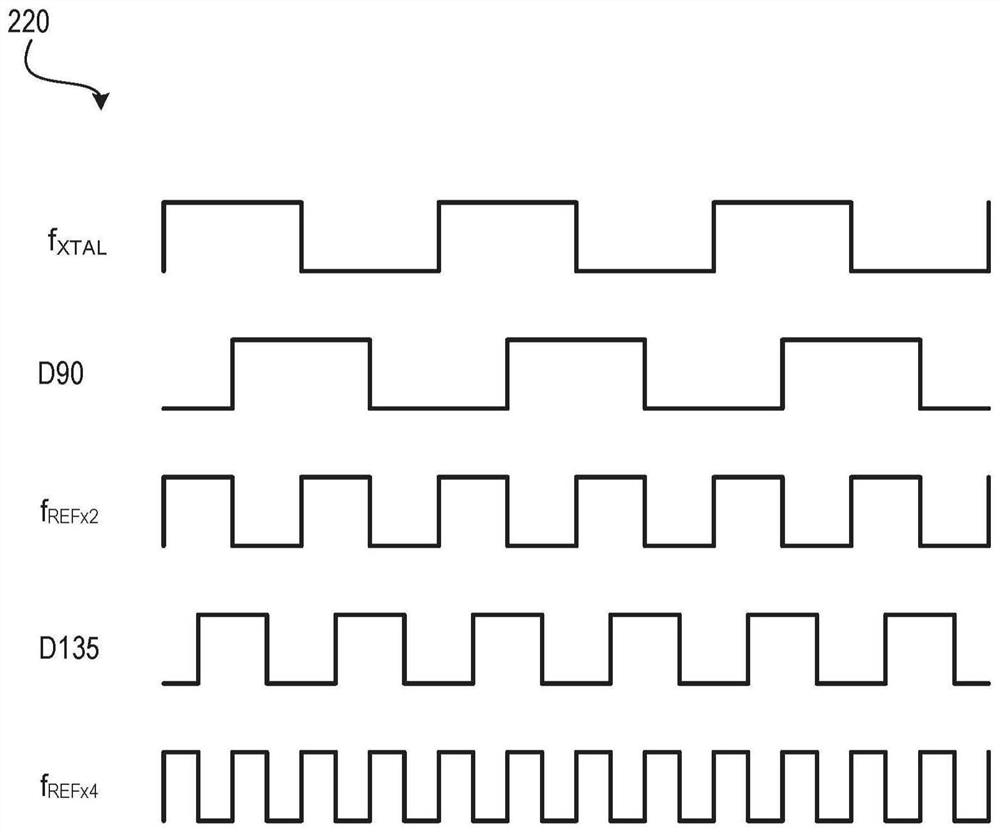
Disclosed are a low power apparatus and method to multiply frequency of a clock. A multi-feedback circuit that compares a duty cycle corrected reference clock fREF, and controls a number of identical delay lines to generate a new clock with a frequency that is a multiple (e.g., 32*, 4*, etc.) of the frequency of fREF with approximately 50% duty cycle (DC). The new clock is used as a reference clock to a phase locked loop (PLL) or a multiplying delay locked loop (MDLL) resulting in shorter lock times for the PLL / MDLL, higher bandwidth for the PLL / MDLL, lower long-term output clock jitter. The multi-feedback circuit can also be used as a low power clock generator.

Description

technical field [0001] The present disclosure relates to low power devices and methods for clock multiplication. Background technique [0002] An external crystal (XTAL) provides the root reference clock frequency for the processor's phase-locked loop (PLL). Due to power consumption, phase noise and cost considerations, the reference clock frequency is usually limited to no more than 100MHz. 38.4MHz off-die XTAL is widely accepted on many computer platforms. For any PLL of the processor, its input reference clock frequency (f REF ) to set its maximum stable loop bandwidth (approximately f REF 10% of The higher the PLL bandwidth, the shorter the settling and / or lock time and the lower the long-term PLL output clock jitter. However, low root reference clock frequency results in lower PLL bandwidth. A lower PLL bandwidth filters out less PLL oscillator noise and increases PLL lock and / or settling time. For a given PLL output frequency, low f REF The feedback divider rat...

Claims


Application Information

Patent Timeline
Patent Type & Authority Applications(China)
IPC IPC(8): H03L7/18
CPCH03L7/18H03K5/1565H03L7/0814H03L7/07H03L7/0818H03L7/087
Inventor 沈冠岳纳赛尔·库尔德
Owner INTEL CORP
Features
  • Generate Ideas
  • Intellectual Property
  • Life Sciences
  • Materials
  • Tech Scout
  • Unparalleled Data Quality
  • Higher Quality Content
  • 60% Fewer Hallucinations
Learn More