Electric-powered actuator and electric braking device

An actuator, electric technology, applied in the direction of braking transmission, motor generator control, transmission control, etc., can solve the problem that the vehicle cannot start

Active Publication Date: 2021-11-09
NTN CORP
View PDF13 Cites 0 Cited by
  • Summary
  • Abstract
  • Description
  • Claims
  • Application Information

AI Technical Summary

Problems solved by technology

For example, if the reverse input holding mechanism is applied to the parking brake function part of the electric brake device using an electric actuator, if the transition to the reverse input holding state, that is, the parking brake state fails, an inclination will occur. The problem is that the vehicle on the road moves on the inclined road contrary to the driver's intention, and if the parking brake fails to be released, the vehicle cannot start.

Method used


Image

  • Electric-powered actuator and electric braking device
  • Electric-powered actuator and electric braking device
  • Electric-powered actuator and electric braking device

Examples


no. 1 Embodiment approach

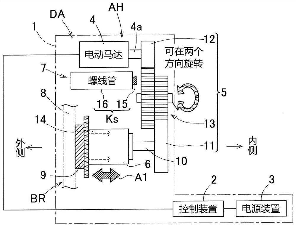
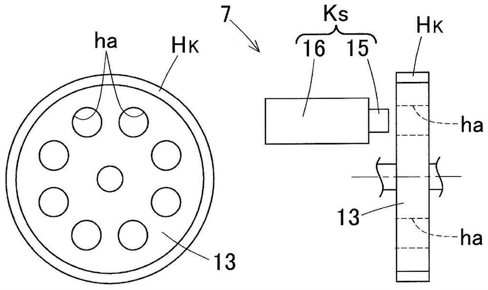
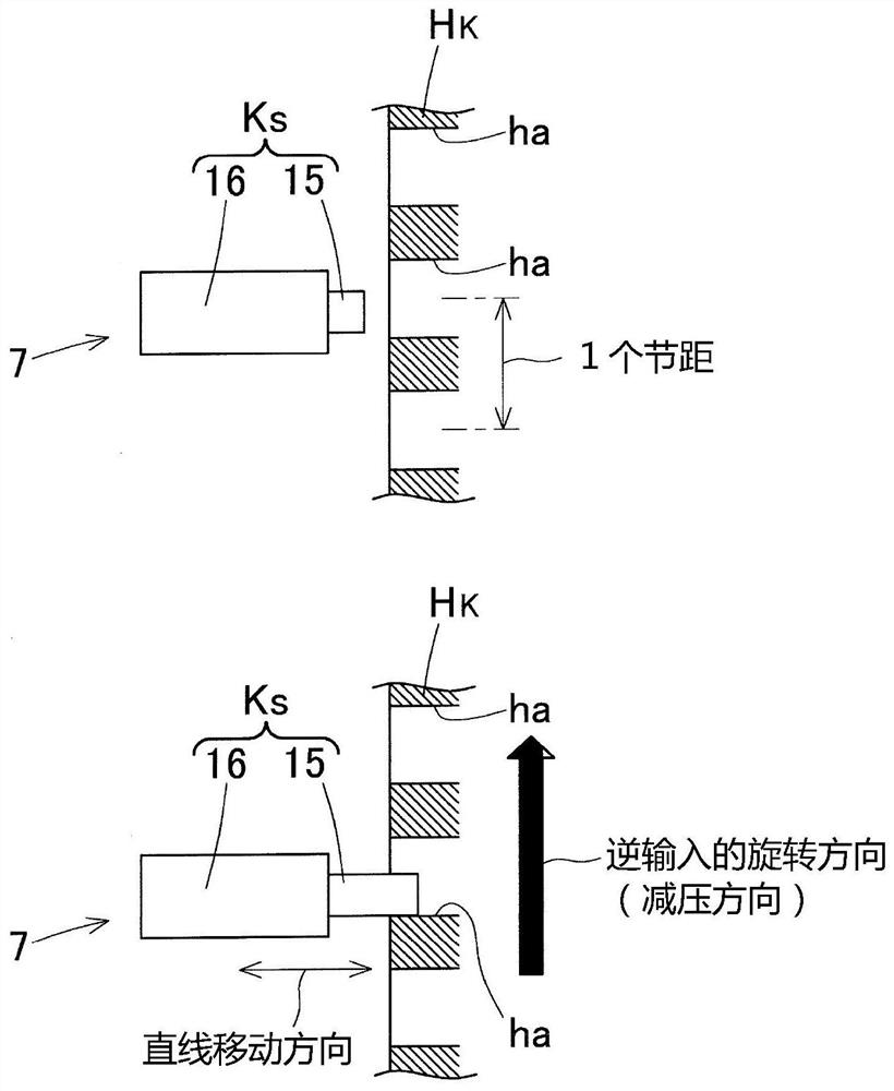
[0073] Combine Figures 1 to 14 The electric brake device having an electric actuator according to the embodiment of the present invention will be described. The electric brake device is mounted on a vehicle. like figure 1 As shown, the electric brake device 1 has an electric actuator DA and a friction brake BR. First, the structure of the electric actuator DA and the friction brake BR will be described.

[0074]

[0075] The electric actuator DA includes an actuator body AH, a power supply device 3, and a control device 2 described later. The actuator body AH has an electric motor 4, a linear moving mechanism 6, a speed reducer 5, a parking brake mechanism 7, an angle sensor SA ( Figure 4 ), Load sensor SB ( Figure 4 . like Figure 4 As shown, the brake actuator BA is composed of an actuator body AH and a friction brake BR.

[0076] like figure 1 with Figure 4 As shown, the electric motor 4 has a rotor and a stator, for example, by a synchronous motor of a permanent magnet. As the...

Embodiment approach

[0156] Next, another embodiment will be described other embodiments. In the following description, the same reference numerals corresponding to each of the items in the first embodiment described embodiments part, overlapping description is omitted. In the case where only a portion of the structure description, unless otherwise specified, the rest of the configuration is the same as the previously described embodiment. Serve the same effect by the same structure. Not only the combination of parts described in the embodiments specifically described, as long as no particular impediment to the combination, the embodiment may be partially combined with each other.

[0157]

[0158] Figure 15A Further provided showing the rotation axis direction of the intermediate gear reducer 5 engaging member 13 rotate synchronously rotating shaft 32 (engaged portion), and an example of a radial groove provided on mz the engaging member 32. Mz the groove in any direction with respect to the rotati...


PUM


Abstract

Provided are an electric-powered actuator (DA) and an electric braking device with which it is possible to effectively operate a reverse-input holding mechanism, and to reduce cost. A control device (2) for this electric-powered actuator comprises: a motor angle estimation means (22a); and a reverse-input holding control unit (24) that has a function in which the electric-powered actuator controls a solenoid (16) when a load is applied, whereby an engagement part (15) is caused to engage with an engaged part and a parking brake mechanism (7) is placed in a reverse-input holding state, and a function in which the engagement part (15) is caused to disengage from the engaged part and the parking brake mechanism (7) is switched from the reverse-input holding state to a reverse-input holding release state. The reverse-input holding control unit (24) has an engagement intermediate control function unit (24a) that controls an estimated rotation angle so that, when the engagement part (15) is caused to engage with the engaged part, and when the engagement part (15) is disengaged from the engaged part, the engaged part and the engagement part (15) reach a set positional relationship within a fixed period of time.

Description

[0001] Application [0002] The present application claims that the date of the application is the priority of the application No. 2019, the application No. 2019-062114, is incorporated herein by reference. Technical field [0003] The present invention relates to an electric actuator and an electric brake device mounted on a vehicle or the like. Background technique [0004] As an electric actuator, the following techniques are proposed. [0005] 1. A electric actuator with a vehicle brake function, in which a snap mechanism is provided on the outer circumference of the ratchet (Patent Document 1). [0006] 2. Electric actuators of the planet wheels and electric motors (Patent Document 2). [0007] Prior art literature [0008] Patent document [0009] Patent Document 1: JP Trunar Number 2006-183809 [0010] Patent Document 2: JP Trunked No. 2006-194356 Inventive content [0011] Subject to solve problems [0012] For example, such as the parking brake mechanism in the electric ...

Claims


Application Information

Patent Timeline
Patent Type & Authority Applications(China)
IPC IPC(8): F16D65/18F16D121/24F16D127/06F16D129/08B60T13/74B60T8/00
CPCB60T8/00B60T13/741B60T1/005F16D63/006B60T1/062F16H63/3441F16D2121/24F16D2127/06F16D65/005F16D55/02B60T1/065H02P3/025H02P15/02F16H63/3466F16H63/483B60T8/17B60T13/746F16D65/18
Inventor 增田唯
Owner NTN CORP
Why Eureka
Try Eureka